Eureka AIR delivers breakthrough ideas for toughest innovation challenges, trusted by R&D personnel around the world.

Efficient garbage treatment device

A waste treatment equipment and high-efficiency technology, applied in the direction of magnetic separation, solid separation, chemical instruments and methods, etc., can solve problems such as waste of resources, impact on environmental sanitation, waste of land, etc., to meet the needs of use, easy to use, and provide efficiency Effect

Active Publication Date: 2017-09-15
中山市程博工业产品设计有限公司
View PDF9 Cites 5 Cited by
  • Summary
  • Abstract
  • Description
  • Claims
  • Application Information

AI Technical Summary

Problems solved by technology

[0002] Garbage is solid waste generated in human daily life and production. Due to the large amount of discharge, complex and diverse components, and polluting, resourceful and social nature, it needs harmless, resourceful, reduction and socialized treatment. If it is not handled properly, it will pollute the environment, affect environmental sanitation, waste resources, and destroy production and living safety. There are more or less metal objects and residual liquids in general garbage, especially metal objects are recyclable resources. , it is necessary to sort the garbage first, and then transport it to other equipment for treatment, which not only reduces the efficiency of garbage treatment but also increases labor costs, etc. In addition, the general garbage treatment is accumulated through burial, which not only wastes land but also may cause secondary pollution Wait
[0003] The existing garbage disposal equipment uses mechanical grippers to pick up the metal in the garbage. The garbage disposal efficiency is low and cannot meet people's needs.

Method used


Image

  • Efficient garbage treatment device
  • Efficient garbage treatment device
  • Efficient garbage treatment device

Examples


Embodiment Construction

[0025] The present invention will be further described below in conjunction with accompanying drawing description and specific embodiment:

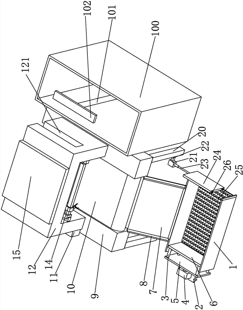
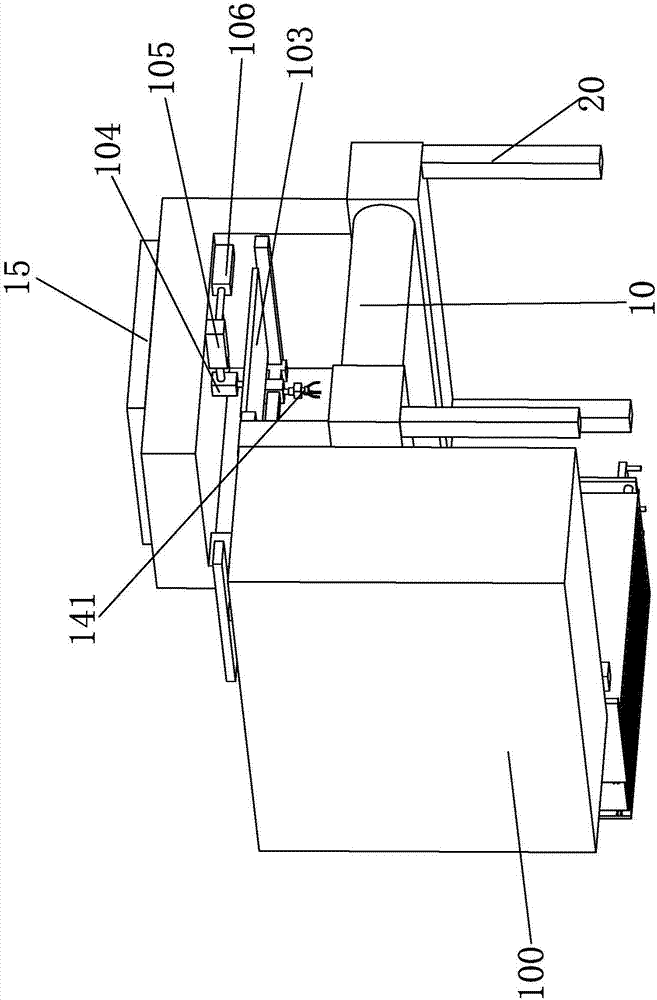
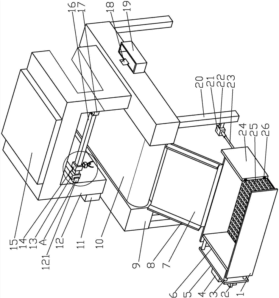
[0026] Such as Figures 1 to 6 The shown a kind of high-efficiency garbage disposal equipment includes a workbench 9, a tripod 20 is provided at the four corners of the lower surface of the workbench 9, a conveyor belt 10 is arranged in the middle of the workbench 9, and a conveyor belt 10 is arranged at the middle of the workbench 9. The middle part of the upper surface is provided with a U-shaped plate 12, and the left side of the U-shaped plate 12 is provided with a single-chip microcomputer 11, and the upper surface of the U-shaped plate 12 is provided with a metal detector 15. 12 is provided with a grabbing mechanism 141 capable of grabbing metal, and an inclined plate 7 is fixedly connected between the workbenches 9 below the outlet end of the conveyor belt 10, and a storage box 1 is provided at the lower end of the inclined plate 7...


PUM


Abstract

The invention discloses an efficient garbage treatment device. The efficient garbage treatment device comprises a workbench, and foot stands are arranged at the four corners of the lower surface of the workbench; a conveyer belt is arranged in the middle of the workbench; a U-shaped plate is arranged in the middle of the upper surface of the workbench; a metal detector is arranged on the upper surface of the U-shaped plate; a grabbing mechanism capable of grabbing metals is arranged in the U-shaped plate; an inclined plate is fixedly connected in the position, below the output end of the conveyer belt, in the middle of the workbench; and a storage box is arranged at the lower end of the inclined plate. The efficient garbage treatment device is characterized in that a sucking mechanism capable of sucking magnetic metals is arranged in the U-shaped plate; a second storage box is arranged on one side of the workbench; a through groove is formed in the side, corresponding to the second storage box, of the U-shaped plate; a moving mechanism capable of driving the sucking mechanism to the position above the second storage box is arranged on the sucking mechanism; and a scraping mechanism capable of scraping the metals on the sucking mechanism into the second storage box is arranged on the second storage box.

Description

technical field [0001] The invention relates to the field of garbage disposal, in particular to high-efficiency garbage disposal equipment. Background technique [0002] Garbage is solid waste generated in human daily life and production. Due to the large amount of discharge, complex and diverse components, and polluting, resourceful and social nature, it needs harmless, resourceful, reduction and socialized treatment. If it is not handled properly, it will pollute the environment, affect environmental sanitation, waste resources, and destroy production and living safety. There are more or less metal objects and residual liquids in general garbage, especially metal objects are recyclable resources. , it is necessary to sort the garbage first, and then transport it to other equipment for treatment, which not only reduces the efficiency of garbage treatment but also increases labor costs, etc. In addition, the general garbage treatment is accumulated through burial, which not ...

Claims


Application Information

Patent Timeline
Patent Type & Authority Applications(China)
IPC IPC(8): B03C1/18B09B3/00
CPCB03C1/18B09B3/00
Inventor 陈伟景
Owner 中山市程博工业产品设计有限公司
Why Eureka
Eureka Blog
Learn More