
Mounting structure of computer numerical control (CNC) drilling machine

An installation structure, technology of CNC drilling machine, applied in the direction of boring/drilling, drilling/drilling equipment, metal processing equipment, etc., can solve the problem of affecting the quality and accuracy of the hole, the tilt of the drill bit installation, the use of the CNC drilling machine is not flexible enough, etc. problems, to achieve the effect of flexible use and avoid installation tilt

Inactive Publication Date: 2017-09-15
芜湖通瑞数控科技有限公司
View PDF0 Cites 3 Cited by
  • Summary
  • Abstract
  • Description
  • Claims
  • Application Information

AI Technical Summary

Problems solved by technology

[0003] However, due to the limitation of the installation structure of the CNC drilling machine, most of the drill body of the existing CNC drilling machine can only move vertically or horizontally. Therefore, when it is necessary to drill inclined holes under special circumstances, the existing CNC drilling machine is not flexible enough. Therefore, it is necessary to optimize the installation structure of the existing CNC drilling machine
At the same time, the installation structure of the existing CNC drilling machine does not have a levelness adjustment device, so when the worker installs the CNC drilling machine, it is inevitable that the drill bit will be installed tilted, which will affect the quality and accuracy of the hole.

Method used


Image

  • Mounting structure of computer numerical control (CNC) drilling machine
  • Mounting structure of computer numerical control (CNC) drilling machine

Examples


Embodiment Construction

[0016] The following will clearly and completely describe the technical solutions in the embodiments of the present invention with reference to the accompanying drawings in the embodiments of the present invention. Obviously, the described embodiments are only some, not all, embodiments of the present invention.

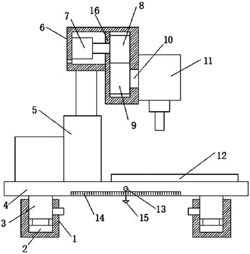
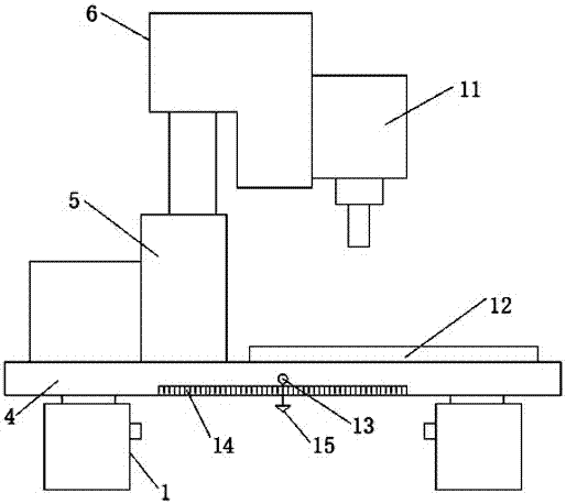
[0017] refer to Figure 1-2 , an installation structure of a numerically controlled drilling machine, comprising a support shell 1, the support shell 1 is a hollow structure with an open top, and a push rod motor 2 is fixed inside the support shell 1, and a support slider 3 is fixed on the output shaft of the push rod motor 2 , the support slider 3 is slidably socketed inside the support shell 1, and the end of the support slider 3 away from the push rod motor 2 is fixed with a workbench 4 above the top of the support shell 1, and a hydraulic pump is fixed above the top of the workbench 4 5, and the piston rod of the hydraulic pump 5 is fixed with an installation she...


PUM


Abstract

The invention discloses an installation structure of a numerical control drilling machine, which comprises a support shell, the support shell is a hollow structure with an open top, and a push rod motor is fixed inside the support shell, and a support slide motor is fixed on the output shaft of the push rod motor. block, the support slider is slidably socketed inside the support shell, and the end of the support slide away from the push rod motor is fixed with a workbench above the top of the support shell, a hydraulic pump is fixed above the top of the workbench, and the hydraulic pump The piston rod of the piston rod is fixed with an installation shell, and a partition is fixed inside the installation shell, and one side of the partition is provided with a drive motor fixed inside the installation shell. The present invention can not only adjust the height of the workbench, but also adjust the installation level of the workbench through the combined use of the set push rod motor, supporting slider, hammer ball and leveling scale, so as to prevent the drill body from being installed and tilted. Cause the problem of punching quality and precision is not high.

Description

technical field [0001] The invention relates to the technical field of drilling machine accessories, in particular to an installation structure of a numerically controlled drilling machine. Background technique [0002] CNC drilling machines are mainly used for drilling, reaming, reaming, tapping and other processing. In the automobile, locomotive, shipbuilding, aerospace, engineering machinery industries; especially for the drilling of various large-scale parts such as ultra-long stacked plates, longitudinal beams, structural steel, and tubular parts, it is the first choice. [0003] However, due to the limitation of the installation structure of the CNC drilling machine, most of the drill body of the existing CNC drilling machine can only move vertically or horizontally. Therefore, when it is necessary to drill inclined holes under special circumstances, the existing CNC drilling machine is not flexible enough. Therefore, it is necessary to optimize the installation struc...

Claims


Application Information

Patent Timeline
IPC IPC(8): B23B39/24
CPCB23B39/24
Inventor 张民胜
Owner 芜湖通瑞数控科技有限公司
Learn More