
Blisk blade circulating milling rigidity reinforcing method

An integral blisk and rigidity enhancement technology, applied in milling machine equipment, milling machine equipment details, program control, etc., can solve the problems of increasing processing difficulty, long non-processing time, and increasing processing cycle, so as to increase non-processing time and improve the surface Quality, the effect of avoiding knife marks

Active Publication Date: 2017-09-15
SHENYANG LIMING AERO-ENGINE GROUP CORPORATION
View PDF6 Cites 6 Cited by
  • Summary
  • Abstract
  • Description
  • Claims
  • Application Information

AI Technical Summary

Problems solved by technology

The method of filling material needs to be filled multiple times during the use process, especially when the blade shape is milled at one time, it needs 3 to 4 times of filling, the non-processing time is longer, and different filling materials have different effects on cutting fluids, etc. affect, or even affect processing; layered processing can effectively enhance the rigidity of parts, but there will be tool marks between layers during processing, and the subsequent light decoration of the blade surface must be done by clamping, increasing The processing cycle is shortened, and at the same time, the repair personnel are required to have a certain level of skill; the way of adding the outer ring is to add a process ring on the outside of the blisk, and use the closed milling method to process the blade shape. This method increases the processing difficulty. It is also necessary to consider the removal of the outer ring

Method used


Image

  • Blisk blade circulating milling rigidity reinforcing method
  • Blisk blade circulating milling rigidity reinforcing method
  • Blisk blade circulating milling rigidity reinforcing method

Examples


Embodiment

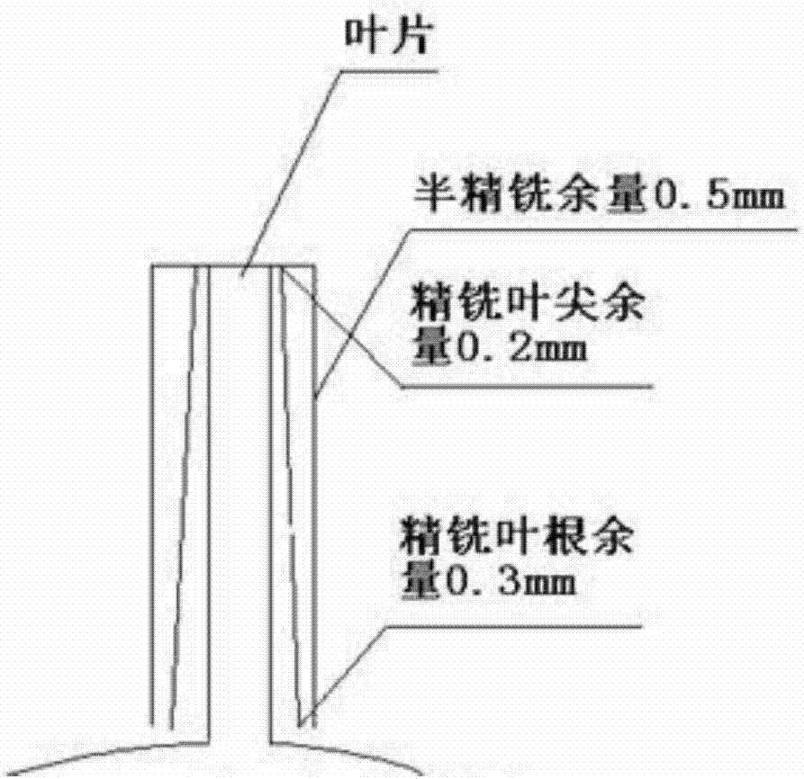
[0043] The overall blisk is made of titanium alloy, the maximum outer diameter of the blade: Φ532mm; the minimum outer diameter of the blade: Φ460mm; the maximum chord width of the blade: 26.5mm; the total number of blades: 79 pieces; the minimum distance between adjacent blades: about 10mm;

[0044] Proceed as follows:

[0045] 1) Determine the fine milling and semi-finishing allowance of the airfoil: here, the half-finishing allowance of the airfoil is selected as 0.5mm; the fine milling allowance is distributed according to the gradient, and the blade tip is set to 0.2mm, and the blade root is 0.3mm .

[0046] 2) Choose the right tool;

[0047] According to the minimum distance between adjacent blades, a ball-end milling cutter with a diameter of Φ8mm is initially selected. After calculation, the diameter of the cutter meets the requirements of semi-finishing and finishing milling programs; after consulting the tool manual, the tool life meets the requirements.

[0048] 3) ...


PUM


Abstract

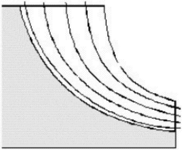
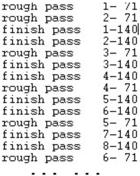
The invention discloses a blisk blade circulating milling rigidity reinforcing method. According to the method, tool paths of semi-finish milling and finish milling in the machining process are combined circularly in combination with allowance distribution, the system rigidity can be improved, and tool marks are avoided; according to the rigidity of blade profiles, the finish milling allowance and the semi-finish milling allowance of the blade profiles are determined; according to the leafing length of the blade profiles and the maximum thickness of blade tips, the rigidity of the blade profiles is judged, generally, the finish milling allowance of the blade tips is set to be 0.2 mm, the finish milling allowance of blade roots is set to be 0.3 mm, and the allowances change in a gradient mode and can be adjusted according to actual conditions; and the semi-finish milling rigidity of the blade profiles needs to be guaranteed in the process, chattering is avoided during machining, and the semi-finish milling allowance is generally set to be 0.5 mm. The machining efficiency is improved, and good surface quality is achieved. Defects of other rigidity reinforcing methods are overcome, the non-machining time is not prolonged, the tool marks are avoided, no additional working procedure is needed, and the machining method is reliable, convenient and fast to implement.

Description

technical field [0001] The invention relates to the field of aero-engine blade processing technology, in particular to a method for enhancing the rigidity of an integral blisk blade through cyclic milling Background technique [0002] The blade processing of the overall blisk belongs to the processing of thin-walled parts. The ratio of leaf span, chord length, and thickness (the maximum thickness of the blade tip) of the airfoil often reaches 40:20:1, which is a typical thin-walled part. During the machining process, many means to enhance the rigidity of the system are needed to obtain high machining efficiency and surface quality of parts. Such as filling materials, layered processing, adding outer rings (closed leaf ring processing) and other methods. The method of filling material needs to be filled multiple times during the use process, especially when the blade shape is milled at one time, it needs 3 to 4 times of filling, the non-processing time is longer, and differ...

Claims


Application Information

Patent Timeline
Patent Type & Authority Applications(China)
IPC IPC(8): B23C3/18G05B19/4099
CPCB23C3/18G05B19/4099
Inventor 杨楠徐一鸣韩德印张莹佟春雷
Owner SHENYANG LIMING AERO-ENGINE GROUP CORPORATION
Learn More