
Floating press-fitting device

A press-fit device and floating connection technology, applied in the field of press-fit devices, can solve the problems of low support force, short stroke of hydraulic support cylinder, unstable press-fit, etc., and achieve low success rate of improvement, wide adaptability, and convenient removal put the effect

Pending Publication Date: 2017-09-15
JIANGYIN BOYAN MACHINERY EQUIP
View PDF9 Cites 21 Cited by
  • Summary
  • Abstract
  • Description
  • Claims
  • Application Information

AI Technical Summary

Problems solved by technology

[0004] At present, there are two press-fitting methods: Method 1. After the workpiece is fixed by the workpiece clamping device, the pressed part is directly pressed into the process hole through a power unit such as a cylinder, oil cylinder or electric cylinder. When the workpiece is an irregular workpiece, In this method, when the workpiece is pressed, since the workpiece clamping device extends into the cavity in the middle of the workpiece through the positioning shaft for support and positioning, when the size of the reverse support surface and the positioning center of the workpiece are greatly changed during the press-fitting of the workpiece, the workpiece will be damaged when it is directly pressed. Uncontrollable factors such as tilting and deformation lead to defects such as low success rate of press-fitting and unstable press-fitting size; Method 2: After the workpiece is fixed by the workpiece clamping device, when the back of the press-fitting hole is suspended, hydraulic pressure is installed on the reverse side. The support cylinder is used for support, and then the pressed part is pressed into the process hole through the power unit. However, because the stroke of the hydraulic support cylinder is very short and the support force is not strong, when the workpiece is of special shape or the geometric structure of the blank is complex, it will also lead to pick-and-place Inconvenient workpiece, unstable pressing and other defects

Method used


Image

  • Floating press-fitting device
  • Floating press-fitting device
  • Floating press-fitting device

Examples


Embodiment Construction

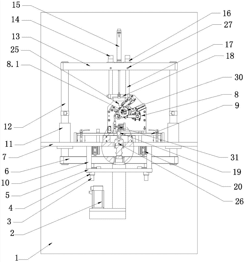
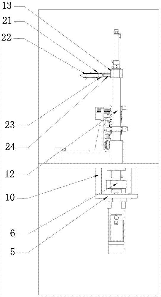
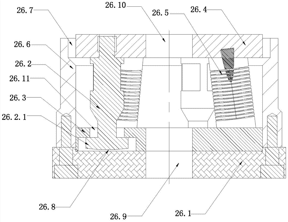
[0021] like figure 1 and figure 2 As shown, a floating press-fit device is characterized in that it includes a frame 1, a press-fit power unit 2, a floating guide shaft 3, a guide sleeve 4, a support plate 5, a power unit mounting plate 6, a workbench panel 7, a workpiece Clamping device 8, fixture table panel 9, fixed connecting rod 10, linear bearing 11, floating connecting column 12, beam 13, dead block 14, lifting cylinder 15, keyway guide sleeve 16, keyway guide rod 17, lifting connecting plate 18 , pressure head 19, floating connector 20, cylinder support 21, locking cylinder 22, locking rod connecting plate 23, locking rod 24, profiling support block 25 and pressure head floating device 26; press-fit power unit 2 is a servo electric cylinder, the floating connector 20 is an air cylinder;

[0022] The workbench panel 7 is fixed on the middle part 1 of the frame, the fixture table panel 9 is arranged on the workbench panel 7, the workpiece clamping device 8 is arranged...


PUM


Abstract

The invention relates to a floating press-fitting device which is characterized by comprising a rack, a press-fitting power unit, floating guiding shafts, guiding sleeves, a supporting plate, a power unit mounting plate, a workbench panel, a workpiece clamping device, a clamp table panel, fixing-connecting rods, linear bearings, floating connecting columns, a cross beam, dead stop blocks, a lifting air cylinder, keyway guiding sleeves, keyway guiding rods, a lifting connecting plate, a press head, a floating connecting part, an air cylinder bracket, a locking air cylinder; a locking rod connecting plate, a locking rod and a profiling supporting block. The floating press-fitting device provided by the invention has the advantages that parts of various types and workpieces of various structures can be subjected to stable press-fitting; in the workpiece press-fitting process, uncontrollable factors such as the inclination and the deformation can be avoided, the press-fitting success rate and the press-fitting size stability can be improved, and the press-fitting workpieces can be conveniently taken and placed; during the press-fitting, the press-fitting power unit can be voluntarily regulated in a floating manner along with changes in the press-fitting position, thereby automatically adapting to the workpiece press-fitting state; and accordingly, the press-fitting of products of different structures and shapes can be achieved.

Description

technical field [0001] The invention relates to a pressing device, in particular to a floating pressing device. Background technique [0002] Some workpieces in industrial production need to process a process hole on the workpiece due to the processing technology and use requirements, such as the turbine casing. According to the design requirements, process plugs, bulkheads, pins, conduits, and linings of other materials need to be pressed into this hole. sleeves, bushings, guide sleeves and other parts to meet the technical requirements of the parts. [0003] The existing press-fitting device includes a frame, a worktable panel, a workpiece clamping device, a fixture table panel and a press-fit power unit. The workbench panel is arranged on the frame, and the workpiece clamping device is arranged on the worktable panel through the fixture table panel Above, the press-fit power unit is set on the frame above the workpiece clamping device, and the press-fit power unit is a p...

Claims


Application Information

Patent Timeline
IPC IPC(8): B23P19/02B23P19/027
CPCB23P19/02B23P19/027
Inventor 张小红李良冯佳陈畅程光辉
Owner JIANGYIN BOYAN MACHINERY EQUIP
Learn More