Supercharge Your Innovation With Domain-Expert AI Agents!

Method for using mold used for punching spiral hole in sponge inner core

A spiral hole, inner core technology, applied in metal processing and other directions, can solve the problems of human discomfort, breathing resistance, insufficient gas flow, etc., and achieve the effects of avoiding discomfort, increasing humidity, and large airflow.

Inactive Publication Date: 2017-09-15
SUZHOU HUICHENG ZHIZAO IND DESIGN
View PDF8 Cites 0 Cited by
  • Summary
  • Abstract
  • Description
  • Claims
  • Application Information

AI Technical Summary

Problems solved by technology

Usually, in order to block dust, people can wear masks to go out, but masks still have a lot of inconvenience, such as some occupations such as traffic police also stipulate that masks cannot be worn.
Now, there is also a nasal filter that can filter some viruses and fine particles (including PM2.5, PM10, etc.). It will also form resistance to human breathing and cause discomfort to the human body. This resistance will lead to insufficient gas flow of the human body. Insufficient gas flow will easily cause hypoxia in the body. If this happens for a long time, it will cause memory loss and increased blood pressure, etc., especially for the body itself. People with respiratory diseases are more uncomfortable and affect their health
[0003] It is necessary to obtain a dust removal and humidification device that does not cover the face, and the inner core of the dust removal humidifier in the nasal cavity is made of soft sponge material, the dust is removed through the inner core spiral pipe, and the solution of adding water to the inner core to increase the inhalation humidity works well. Solve the shortcomings of existing masks and nasal filters, however, because the sponge is a soft material, it is difficult to make through holes, especially spiral through holes

Method used


Image

  • Method for using mold used for punching spiral hole in sponge inner core
  • Method for using mold used for punching spiral hole in sponge inner core
  • Method for using mold used for punching spiral hole in sponge inner core

Examples


Embodiment 1

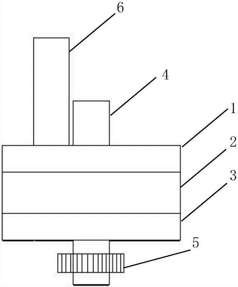
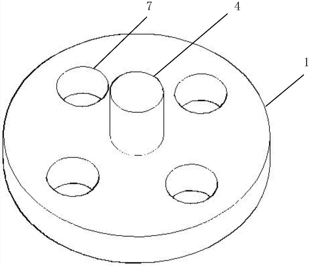
[0033] Example 1: With reference to the drawings, a mold for punching spiral holes in a sponge core includes an upper mold 1, a lower mold 3, and the upper mold 1 and the lower mold 3 are respectively provided with a mold handle 4, a mold hole 7 and The mold surface is provided with positioning pins 8, the lower mold 3, the mold handle 4 is provided with a gear 5, the gear 5 drives the lower mold 3 to rotate a predetermined angle, and the upper mold 1 is provided with a punch hole 7 After closing the mold, the punch 6 punches into the die hole 7 of the lower mold 3.

[0034] In a preferred technical solution, the positioning pin 8 is tapered and has a height of 1-2 mm.

[0035] In a preferred technical solution, the punch 6 is hollow and tubular, and the lower end is provided with a flat knife edge or an inclined knife edge.

[0036] In a preferred technical solution, the gear 5 is connected to the power mechanism, and the gear 5 drives the lower mold 3 to rotate 90°-360°, especiall...


PUM

PropertyMeasurementUnit
heightaaaaaaaaaa

Abstract

The invention aims at providing a method for using a mold used for punching a spiral hole in a sponge inner core. The method for using the mold used for punching the spiral hole in the sponge inner core comprises an upper mold body and a lower mold body, and the upper mold body and the lower mold body are each provided with a mold shank, a mold hole and a mold surface, wherein each mold surface is provided with positioning needles; the mold shank of the lower mold body is provided with a gear, and the gear drives the lower mold body to rotate by a predetermined angle; and the mold hole of the upper mold body is provided with a punch, and the punch punches into the mold hole of the lower mold body after mold assembling. The sponge inner core is placed between the upper mold surface and the lower mold surface, the lower mold body punches after rotating by the predetermined angle, then the inner core with the spiral hole is obtained, and the inner core is dedusted through the spiral hole. According to the scheme, suction humidity is increased by adding water into the inner core, and the effect is good.

Description

Technical field [0001] The invention belongs to an appliance for arranging spiral holes on soft products, and in particular relates to a method for using a mold for punching spiral holes in a sponge inner core. Background technique [0002] In the north of my country, the climate is dry, and the air contains a large amount of suspended particles and dust, and even dust is generated during strong winds. Some people with allergies cause cough, asthma and other diseases due to inhalation of pollen and dust mites. At the same time, dry air can easily make people irritable, dizziness, chest tightness, and throat and nose discomfort. Generally, in order to block dust, people can wear masks when traveling. However, masks still have many inconveniences. Some occupations such as traffic police also stipulate that masks cannot be worn. Now, there is also a nasal cavity filter that can filter some viruses and fine particles (including PM2.5, PM10, etc.). This filtering effect mainly relie...

Claims


Application Information

Patent Timeline
Patent Type & Authority Applications(China)
IPC IPC(8): B26F1/02B26F1/14B26D3/11
CPCB26D3/11B26F1/0084B26F1/02B26F1/14
Inventor 张朝峰
Owner SUZHOU HUICHENG ZHIZAO IND DESIGN
Features
  • R&D
  • Intellectual Property
  • Life Sciences
  • Materials
  • Tech Scout
  • Unparalleled Data Quality
  • Higher Quality Content
  • 60% Fewer Hallucinations
Learn More