Variable-pitch multi-rotor unmanned aerial vehicle with variable special-shaped structure

A multi-rotor unmanned aerial vehicle, a variant technology, applied in the field of aircraft and unmanned aerial vehicles, to achieve the effect of reducing turbulence, uniform lift distribution, and high level flight speed

Pending Publication Date: 2017-09-15
SICHUAN COLLEGE OF ARCHITECTURAL TECH
View PDF9 Cites 4 Cited by
  • Summary
  • Abstract
  • Description
  • Claims
  • Application Information

AI Technical Summary

Problems solved by technology

[0004] The purpose of the present invention is to provide a variable-distance multi-rotor UAV with a variable structure, which is used to solve the problem of the inability or inconvenience of existing UAVs to change the UAV by adjusting the current positional relationship between the arm and the frame. Center of gravity to adapt to different flight requirements and enhance flight stability; at the same time, provide a UAV that simultaneously changes the pitch angle of the arm and the inclination angle of the rotor blades to meet the needs of UAVs in take-off and landing, level flight, high and low speed The problem of different lift forces required for various attitude transitions in flight

Method used


Image

  • Variable-pitch multi-rotor unmanned aerial vehicle with variable special-shaped structure
  • Variable-pitch multi-rotor unmanned aerial vehicle with variable special-shaped structure
  • Variable-pitch multi-rotor unmanned aerial vehicle with variable special-shaped structure

Examples


Embodiment 1

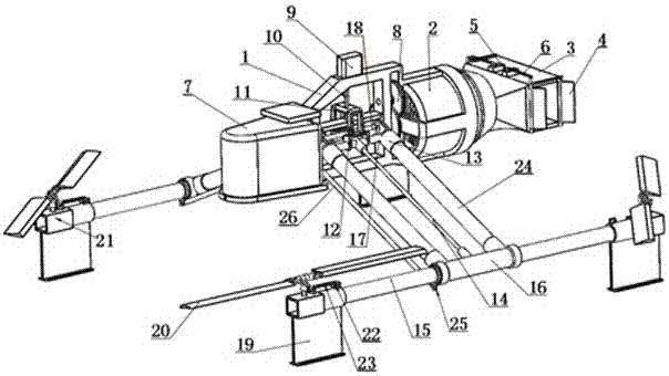
[0038] combined with figure 1 As shown, a variable-pitch multi-rotor UAV with a variable structure includes a frame 1, a power unit installed on the frame 1, a fuel tank 7 for supplying oil to the power unit, and a lift device connected to the power unit. , and an adjustment device for adjusting the pitch angle of the lift device relative to the frame 1, a speed reduction device is arranged between the lift device and the power device, the power device is a turboshaft engine and an exhaust box is connected to the exhaust end 3. A deflector for controlling the direction and flow velocity of the exhaust airflow is installed on the exhaust box 3; the deflector includes deflectors 4 symmetrically installed at both ends of the exhaust box 3, and the two ends are respectively hinged on the The deflector push-pull rod 6 used to control the synchronous deflection of the deflector 4 on the deflector 4, and the deflector control steering gear 5 installed on the exhaust box 3 for driving...

Embodiment 2

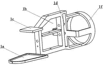
[0043] In order to better realize the present invention, on the basis of embodiment 1, further in conjunction with the attached figure 1 and 3 As shown, the frame 1 is composed of five integrally formed parts, specifically including a power plant mounting seat 1f for mounting the turboshaft engine, and the power plant mounting seat 1f is a hollow cylindrical structure with one end open, And one end away from the opening is provided with an installation cavity 1d for installing the deceleration device 8, and adjacent to the installation cavity 1d is a lift device installation cavity 1b for installing the lift device; and located in the lift device installation cavity 1b An electronic equipment installation seat 1c is provided at the upper end of the side away from the power device installation seat 1f, and a fuel tank installation seat 1a for placing the fuel tank is provided at the lower end of the electronic equipment installation seat 1c. It is worth noting that the electro...

Embodiment 3

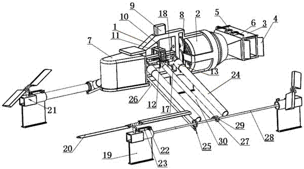
[0045] In order to better realize the present invention, on the basis of the structure and principle of embodiment 2, further in conjunction with the attached Figure 1-3 As shown, the lift device includes support arms symmetrically arranged on both sides of the frame 1 in a T-shape, and the support arms include an arm standpipe 15 arranged parallel to the length direction of the frame 1 and a The machine arm vertical tube 15 is a machine arm horizontal tube 24 arranged at 90°; the machine arm horizontal tube 24 is in principle machine arm vertical tube 15 and one side of the machine arm vertical tube 15 is hinged on the side wall of the lifting device installation chamber 1b and the machine arm horizontal tube 24 The quantity is two that are arranged in parallel; each only end of described machine arm standpipe 15 is provided with the rotor mechanism that is used for providing lift, and described rotor mechanism communicates with the described support arm through the drive sha...


PUM


Abstract

The invention discloses a variable-pitch multi-rotor unmanned aerial vehicle with a variable special-shaped structure. The variable-pitch multi-rotor unmanned aerial vehicle comprises a rack, a power device arranged on the rack, a fuel tank, a lifting device and an adjusting device, wherein a speed reducer is arranged between the lifting force and the power device; an exhaust end of the power device is connected with an exhaust box; the exhaust box is provided with a flow guide device; the flow guide device comprises flow guide plates which are symmetrically arranged at two ends of the exhaust end, a flow guide plate push-pull rod and a flow guide plate control steering engine; two ends of the flow guide plate push-pull rod are hinged with the flow guide plates, and the flow guide plate push-pull rod is used for controlling the flow guide plates to deflect synchronously; and the flow guide plate control steering engine is arranged on the exhaust box and is used for driving the flow guide plate push-pull rod. The lifting device is hinged with the rack, and meanwhile, the adjusting device for adjusting the elevation angle is also arranged between the lifting device and the rack, so that the posture and the gravity center of the unmanned aerial vehicle are changed, and the stability and the high efficiency of the unmanned aerial vehicle under different flight environments and requirements are improved.

Description

technical field [0001] The present invention relates to the field of aircraft, in particular to the field of unmanned aerial vehicles, specifically, a variable-distance multi-rotor unmanned aerial vehicle with a variable structure. Background technique [0002] At present, multi-rotor UAVs are widely used in the fields of reconnaissance, photography, signal emission, and aircraft model research. affect the flight performance of the UAV. At present, the arm connection structure of multi-rotor small drones generally adopts a flat straight-lay structure. Due to the good stability and high structural strength of the flat straight-lay structure, the failure rate of the drone's body structure is relatively low; however, its fixed The structure of the UAV also brings the disadvantages of being non-adjustable and non-deformable, which limits the performance of the UAV in different environments and flight states to a certain extent; Maneuverability, the center of gravity of the UAV...

Claims


Application Information

Patent Timeline
Patent Type & Authority Applications(China)
IPC IPC(8): B64C27/08B64C27/32B64C27/46B64C1/00B64D33/04
CPCB64C1/00B64C27/08B64C27/32B64C27/46B64D33/04
Inventor 严珍凤谢明阳刘辉扬
Owner SICHUAN COLLEGE OF ARCHITECTURAL TECH
Why Eureka
Try Eureka