Cyclic conveying device

A cyclic transmission and sensor technology, applied in conveyors, mechanical conveyors, transportation and packaging, etc., can solve the problems affecting the transmission efficiency of the carrier mechanism.

Inactive Publication Date: 2017-09-15
HANS LASER TECH IND GRP CO LTD
View PDF8 Cites 2 Cited by
  • Summary
  • Abstract
  • Description
  • Claims
  • Application Information

AI Technical Summary

Problems solved by technology

However, the slide rail and the return mechanism in the circular transmission device usually adopt a split mechanism. When the return mechanism transfers the carrier mechanism between the two slide rails, the carrier mechanism is often easy to move relative to the transfer

Method used


Image

  • Cyclic conveying device
  • Cyclic conveying device
  • Cyclic conveying device

Examples


Embodiment Construction

[0026] In order to facilitate the understanding of the present invention, the present invention will be described more fully below with reference to the associated drawings. Preferred embodiments of the invention are shown in the accompanying drawings. However, the present invention can be embodied in many different forms and is not limited to the embodiments described herein. On the contrary, the purpose of providing these embodiments is to make the disclosure of the present invention more thorough and comprehensive.

[0027] It should be noted that when an element is referred to as being “fixed” to another element, it can be directly on the other element or there can also be an intervening element. When an element is referred to as being "connected to" another element, it can be directly connected to the other element or intervening elements may also be present. The terms "vertical," "horizontal," "left," "right," and similar expressions are used herein for purposes of ill...


PUM


Abstract

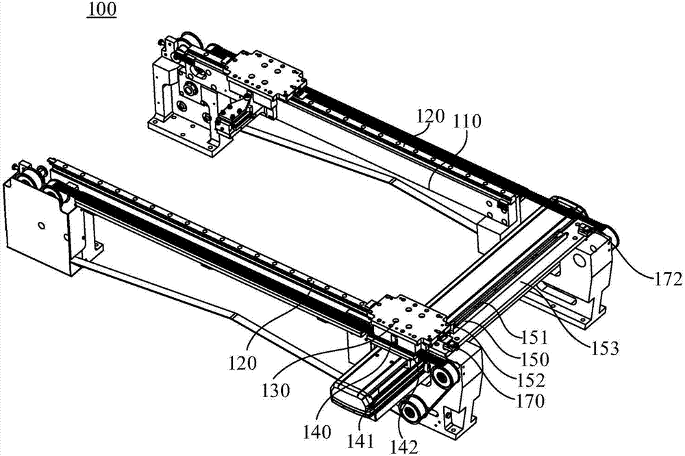
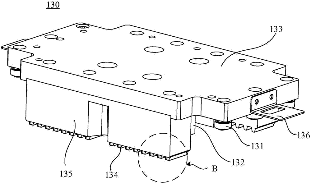
The invention relates to a cyclic conveying device. The cyclic conveying device comprises two racks which are arranged in parallel, a carrying plate mechanism, a return mechanism and an auxiliary block, wherein a slide rail is arranged on each of the two racks; the carrying plate mechanism is slidably born on the slide rails, and a guide wheel is arranged on the carrying plate mechanism; the return mechanism is used for conveying the carrying plate mechanism to a space between the two slide rails, the return mechanism comprises a transferring table and a slide seat, the transferring table is arranged between the two racks, and the slide seat is slidably arranged on the transferring table and used for slidably bearing the carrying plate mechanism; and the auxiliary block is arranged between the two racks, and a guide groove matched with the guide wheel is formed in the auxiliary block. According to the cyclic conveying device, a good guide effect is acted on the movement of the carrying plate mechanism relative to the transferring table through the mutual matching of the guide wheel and the guide groove, the lateral deviation of the carrying plate mechanism relative to the transferring table of the return mechanism is avoided, and the carrying plate mechanism can be smoothly transited to the slide rail at the other side from the slide seat of the return mechanism, so that the conveying efficiency of the carrying plate mechanism is greatly increased.

Description

technical field [0001] The invention relates to the field of automatic transmission equipment, in particular to a circular transmission device. Background technique [0002] A circular conveyor is often required in automated production, and the circular conveyor usually includes a carrier mechanism for carrying jigs, slide rails, and a return mechanism. However, the slide rail and the return mechanism in the circular transmission device usually adopt a split mechanism. When the return mechanism transfers the carrier mechanism between the two slide rails, the carrier mechanism is often easy to move relative to the transfer platform of the return mechanism. The lateral offset occurs, causing the carrier mechanism to fail to smoothly transition from the sliding seat of the return mechanism to the slide rail on the other side, thereby affecting the transmission efficiency of the carrier mechanism. Contents of the invention [0003] Based on this, it is necessary to provide a ...

Claims


Application Information

Patent Timeline
IPC IPC(8): B65G35/06
CPCB65G35/06
Inventor 叶贵青赖文杰谢祖平刘维波蔡石文蒋杰王瑾高云峰
Owner HANS LASER TECH IND GRP CO LTD
Why Eureka
Try Eureka