Subway foundation pit dewatering well with pressure reduction monitoring effect

A technology for dewatering wells and subways, applied in infrastructure engineering, excavation, construction, etc., can solve problems such as wasting groundwater resources, and achieve the effects of protecting safety, avoiding uplift damage, and avoiding losses

Pending Publication Date: 2017-09-15
CCCC TUNNEL ENG
View PDF8 Cites 4 Cited by
  • Summary
  • Abstract
  • Description
  • Claims
  • Application Information

AI Technical Summary

Problems solved by technology

This method has the disadvantage of wasting a large amount of groundwater resources, especially for water-scarce cities in the north represented by Beijing, which has great constraints

Method used


Image

  • Subway foundation pit dewatering well with pressure reduction monitoring effect
  • Subway foundation pit dewatering well with pressure reduction monitoring effect
  • Subway foundation pit dewatering well with pressure reduction monitoring effect

Examples


Embodiment 1

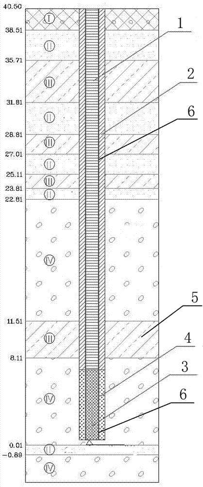
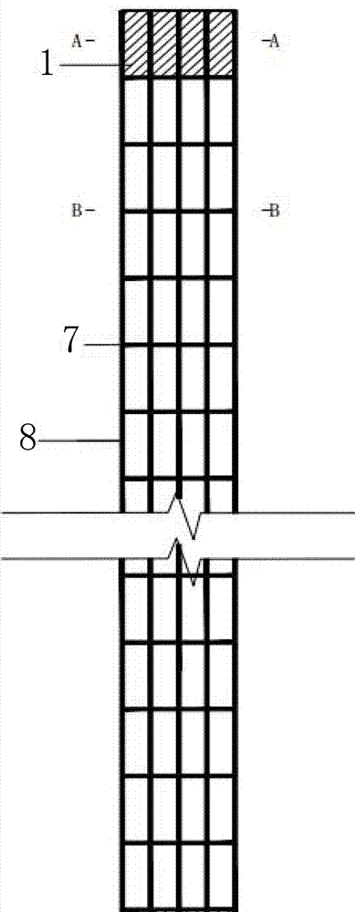
[0027] Such as figure 1 As shown, a subway foundation pit dewatering well with monitoring and decompression effect includes two parts, the water supply layer of the upper layer and the water filter layer of the lower layer, and the steel cage 6 is set in the well to run through the water supply layer and the water filter layer from top to bottom; The water supply layer is provided with a steel pipe 1 inside the steel cage 6, and clay 2 is filled outside the steel cage; the water filter layer is provided with a steel filter pipe 3 inside the steel cage 6, and a double-layer nylon cloth and a filter are arranged outside the steel cage 6. Material 4.

[0028] The dewatering well is set above the groundwater level, and the bottom of the dewatering well is 8.11-11.51m away from the groundwater level; the bottom of the dewatering well penetrates the underground aquifer 5 (8.11-11.51m away from the groundwater level).

[0029] In this example:

[0030] The steel pipe 1 of the water...

Embodiment 2

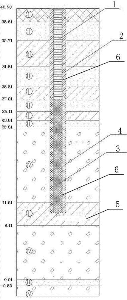
[0035] Such as figure 2 As shown, only the depth of the dewatering well in this embodiment is different from embodiment 1, and other features are the same as in embodiment 1. The bottom of the dewatering well is 0.01 ~ 8.11m away from the groundwater level line; the bottom of the dewatering well does not penetrate the underground septum Water layer 5 (8.11~11.51m away from groundwater level).

[0036] During the process of the project, the construction personnel used the water gauge to measure the water level in the dewatering well. According to the principle of the connector, the water level in the foundation pit is consistent with the water level in the dewatering well. Based on this, it can be judged whether the water level in the foundation pit exceeds the standard. Once it is found that the water level in the foundation pit exceeds the reasonable calculation value, the construction personnel will use the pump to pump the water out of the dewatering well in time, the wate...


PUM


Abstract

The invention discloses a subway foundation pit dewatering well with a pressure reduction monitoring effect. The subway foundation pit dewatering well comprises an upper water feeding layer and a lower water filtering layer, and a steel reinforcement cage is arranged in the well and penetrates through the water feeding layer and the water filtering layer from top to bottom; a steel pipe is arranged on the portion, inside the steel reinforcement cage, of the water feeding layer, and the steel reinforcement cage is externally filled with clay; a steel reinforcement water filtering pipe is arranged on the portion, inside the steel reinforcement cage, of the water filtering layer, and the steel reinforcement cage is externally provided with a double-layer nylon cloth and externally filled with a filtering material. According to the dewatering well device, not only is real-time monitoring on the underground water change condition achieved, but also a guarantee is provided for emergency measures of recharging water in the pit in the foundation pit excavating process, upheaval destruction in the foundation pit excavating process is avoided, therefore, settlement influences of the surrounding ground, traffic, buildings and the like are reduced, the safety of the ambient environment is guaranteed, and unnecessary losses are avoided.

Description

technical field [0001] The invention relates to the field of groundwater safety in the excavation of subway foundation pits, in particular to a dewatering well device for emergency monitoring of groundwater during the excavation of large foundation pits with high pressure water depth, in particular to a dewatering well device for subway foundation pits with the function of monitoring decompression Wells are used to detect changes in groundwater levels and deduce the stability of foundation pit excavation. Background technique [0002] At present, for deep and large foundation pits with highly confined water, the conventional measures are mainly to construct dewatering wells within the excavation range, and to pump groundwater before excavation of the foundation pit to solve the problem. This method has the disadvantage of wasting a large amount of groundwater resources, especially for water-scarce cities in the north represented by Beijing, which has great constraints. [0...

Claims


Application Information

Patent Timeline
Patent Type & Authority Applications(China)
IPC IPC(8): E02D19/10E02D17/02
CPCE02D17/02E02D19/10
Inventor 成晓青刘金山孙建平王旭
Owner CCCC TUNNEL ENG
Why Eureka
Try Eureka