Inserted-type steel truss joint construction for building bridge or building structure

A steel truss and plug-in technology, applied in building construction, bridge construction, bridges, etc., can solve problems such as difficult to break through technical bias, durability affects connection reliability, etc., achieve remarkable technical effects and meet the requirements of mechanical properties , to ensure the overall effect

Active Publication Date: 2017-09-15
BEIJING JIAOTONG UNIV
View PDF5 Cites 6 Cited by
  • Summary
  • Abstract
  • Description
  • Claims
  • Application Information

AI Technical Summary

Problems solved by technology

[0004] In the existing technology, structural adhesives are widely used in engineering practice, but their durability is the key factor affecting the reliability of the connection
[0005] In the existing technology, those skilled in the art have formed the inertia of traditional thinking such as steel truss welding or high-strength bolt connection, and it is difficult to break through technical prejudices, and it is even more difficult to think of new bridges that are convenient for construction and meet various mechanical properties. or building structure node construction

Method used


Image

  • Inserted-type steel truss joint construction for building bridge or building structure
  • Inserted-type steel truss joint construction for building bridge or building structure
  • Inserted-type steel truss joint construction for building bridge or building structure

Examples


Embodiment Construction

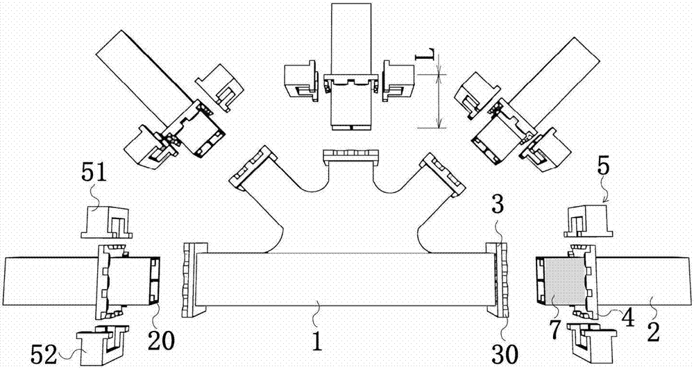
[0028] Such as Figure 1-3 As shown, according to an embodiment of the present invention, the plug-in steel truss node construction includes:

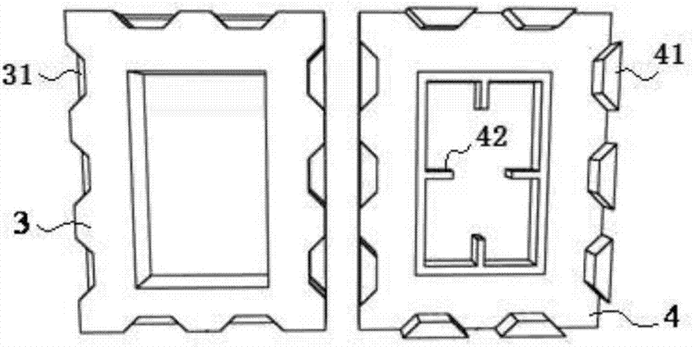
[0029] Steel truss node 1, which has at least one inserted opening, and the end 30 of each inserted opening is provided with an inserted end flange 3;

[0030] A truss member 2, which has an insertion end capable of clearance fit with the inserted end of the steel truss node 1, at the tail of the insertion end opposite to the end 20 of the truss member 2 (with the end 20 The distance is L) there is an insertion end flange 4;

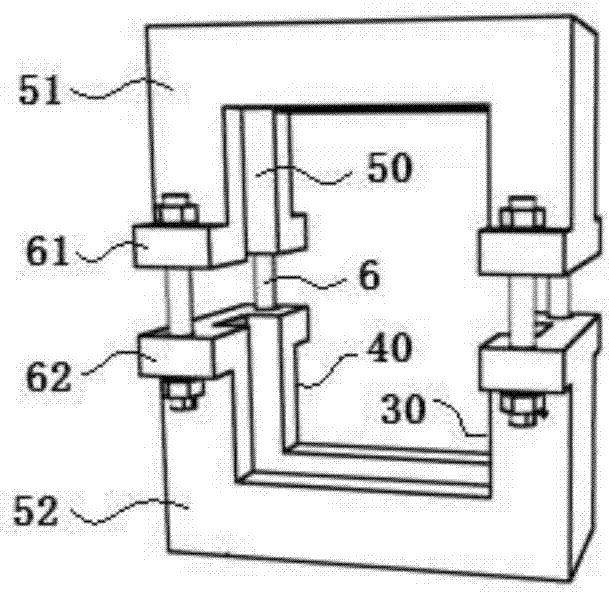
[0031] A fastener 5, which is composed of two halves 51, 52, the fastener 5 is provided with a groove 50 matching the periphery of the inserted end flange 3 and the insertion end flange 4, the groove 50 The width is the sum of the width of the inserted end flange 3 and the width of the inserted end flange 4, and one side of the fastener 5 has an inserted end matched with the inserted end of the steel truss node...


PUM


Abstract

An inserted-type steel truss joint construction comprises a steel truss joint, truss frame rod parts, fasteners, structural adhesives and bolts, wherein at least one be-inserted opening is formed in the steel truss joint, and a be-inserted end flange is arranged at the end of each be-inserted opening; each truss frame rod part is provided with an inserting end which can be in clearance fit with the be-inserted end of the steel truss joint, wherein an inserting end flange is arranged on the tail, opposite to the end of the truss frame rod part, of the inserting end; each fastener is composed of two half parts, a groove is formed in each fastener, and each groove is matched with the peripheries of the corresponding be-inserted end flange and the corresponding inserting end flange, upper half bosses are arranged at the two ends of a closing line of the first half parts of the fasteners, and upper half bolt holes are formed in each upper half boss, while a lower half bosses is arranged at the two ends of a closing line of the second half parts of the fasteners, and lower half bolt holes are arranged on the lower half bosses; structural adhesives are arranged in installing clearances; and the bolts enable the upper half bolt holes to be connected with the lower half bolt holes. The truss frame joint construction is high in construction efficiency, good in reliability, and long in service life.

Description

technical field [0001] The invention relates to a plug-in steel truss node structure for building bridges or building structures, which can shorten the construction period and belongs to the fields of bridge engineering and building engineering. [0002] The plug-in steel truss node according to the present invention can be a prefabricated part, or a welded or assembled part on site. Background technique [0003] In the prior art, general truss joints in bridges and building structures are formed by riveting, welding and connecting high-strength bolts and rods. With the development of welding technology and high-strength bolt connection technology, traditional riveting technology has been gradually eliminated due to the difficulty of on-site construction. Welding and high-strength bolt connections have greatly improved the connection reliability of nodes and rods, and more and more engineering examples have shown that welding can easily lead to changes in the metallographic...

Claims


Application Information

Patent Timeline
Patent Type & Authority Applications(China)
IPC IPC(8): E04B1/58E01D19/00
CPCE01D19/00E04B1/58
Inventor 雷俊卿桂成中黄祖慰曹珊珊刘昊苏
Owner BEIJING JIAOTONG UNIV
Why Eureka
Try Eureka