
LED wall washing lamp

A technology of LED wall washer and LED light source, which is applied in the field of lighting, can solve the problems of easy entry, glue residue, and easy formation of water vapor, etc., so as to avoid the formation of water vapor, better heat dissipation effect, and eliminate potential hidden dangers.

Inactive Publication Date: 2017-09-15
吴世宇
View PDF0 Cites 0 Cited by
  • Summary
  • Abstract
  • Description
  • Claims
  • Application Information

AI Technical Summary

Problems solved by technology

This will easily cause the aging and breakage of the sealant in the lamp body, resulting in failure of the seal, making the external water flow easily into the LED wall washer, thus affecting the LED light source components and other electronic components.
Furthermore, since the water entering the LED wall washer is difficult to flow out, it is easy to remain on the sealant layer of the LED light source assembly, resulting in long-term water accumulation in the sealant layer, which will also affect the LED light source assembly and other electronic components.
For the above situation, in severe cases, it may even cause a short circuit of the LED light source component, resulting in the inability of the LED wall washer to be used.
2. Because the LED wall washer is sealed as a whole, the heat dissipation effect of the LED wall washer is poor; moreover, during the use of the LED wall washer, it is easy to form water vapor, which affects its own lighting effect
3. Since the existing LED wall washers all need sealant, the manufacturing process is relatively complicated, the production efficiency is low, and the production cost is high; moreover, in the process of applying sealant, it is easy to cause glue residue, which affects To the appearance of LED wall washer

Method used


Image

  • LED wall washing lamp
  • LED wall washing lamp
  • LED wall washing lamp

Examples


Embodiment Construction

[0023] Below, in conjunction with accompanying drawing and specific embodiment, the present invention is described further:

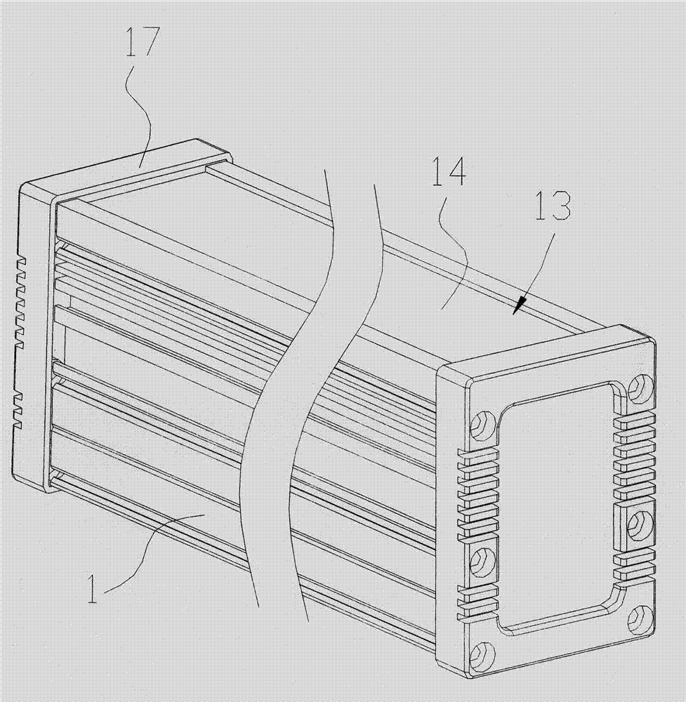
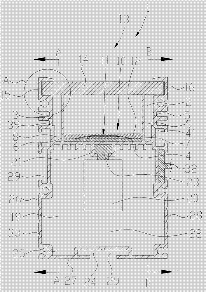
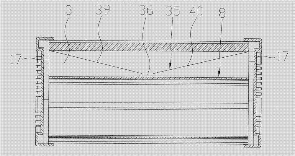
[0024] refer to Figure 1 to Figure 4 , an LED wall washer, comprising a lamp body 1, the lamp body 1 is provided with a first accommodating cavity 2 along its length direction, and the first accommodating cavity 2 includes a first inner wall 3, a second inner wall connected in sequence The inner wall 4 and the third inner wall 5, the second inner wall 4 extends a first baffle 6 and a second baffle 7, and the first baffle 6 and the second baffle 7 are all along the lamp body 1 The length direction of the lamp body 1 is set between the first baffle plate 6 and the first inner wall 3 to form a first drainage groove 8 for draining water to the outside, and the first inner wall 3 is provided with a The first guide slope 35 arranged in the direction, the first guide slope 35 is provided with a first injection port 36, and the first injection port 36 communi...


PUM


Abstract

The invention discloses an LED wall washer lamp, which comprises a lamp body, the lamp body is provided with a first accommodating cavity, a first baffle and a second baffle extend from the second inner wall of the first accommodating cavity, and the first baffle A first drainage groove is formed between the first inner wall, the first inner wall is provided with a first diversion slope, the first diversion slope is provided with a first injection port, the first injection port communicates with the first drainage groove, and the second blocking A second drainage groove is formed between the plate and the third inner wall, the third inner wall is provided with a second diversion slope, the second diversion slope is provided with a second injection port, the second injection port communicates with the second drainage groove, and the first An accommodating groove is formed between the baffle plate and the second baffle plate, the accommodating groove is provided with an LED light source assembly and a sealant layer, a light outlet is formed between the first inner wall and the third inner wall, and a light-transmitting plate is arranged at the light outlet. The first baffle and the second baffle extend to the light-transmitting plate and are attached to the light-transmitting plate. Through the above-mentioned structural setting, the use effect of the product is effectively improved.

Description

technical field [0001] The invention relates to the field of lighting, in particular to an LED wall washer. Background technique [0002] With the improvement of living standards, people's requirements for living environment are getting higher and higher. Therefore, the application of LED wall washers is becoming more and more extensive. For example, LED wall washers are often used in outdoor environments such as squares, bridges, and parks to play the role of decorative lighting and make the outdoor environment more beautiful. Existing LED wall washers generally include a lamp body, which has a housing cavity in which an LED light source assembly is arranged, and a sealant layer is poured into the housing cavity to cover the LED light source assembly; the lamp body also has a light output The LED light source assembly can project light to the outside through the light outlet, and then realize the lighting of the LED wall washer. Since the LED wall washer is mostly used o...

Claims


Application Information

Patent Timeline
Patent Type & Authority Applications(China)
IPC IPC(8): F21S8/00F21V17/16F21V29/503F21V29/56F21V31/00F21Y115/10
CPCF21S8/00F21V17/164F21V29/503F21V29/56F21V31/005F21Y2115/10
Inventor 吴世宇
Owner 吴世宇
Learn More