Pseudo-static testing device for concrete columns after non-peripheral fire exposure and implementation method thereof

A technology of concrete column and test device, which is applied in measurement device, vibration test, test of machine/structural components, etc. Installation of horizontal tension-compression servo loading device, etc.

Active Publication Date: 2017-09-15
HUAQIAO UNIVERSITY
View PDF6 Cites 30 Cited by
  • Summary
  • Abstract
  • Description
  • Claims
  • Application Information

AI Technical Summary

Problems solved by technology

However, there are few experimental research results on the shear bearing capacity and seismic performance of concrete columns after different fire exposure methods.
[0004]The existing post-fire concrete column quasi-static test device and implementation method generally have the following problems: (1) It is difficult for the test device to test the non-fired concrete column The existing quasi-static test results of concrete columns are all based on the situation after the surrounding fire, and there is no report on the research results of the quasi-static test of concrete columns after different fire methods
In order to investigate the influence of different fire exposure methods at high temperature, the existing limited tests use several layers of fireproof cotton on the surface of the test piece and put it into the furnace to conduct fire tests according to the fire exposure method in four directions to approximate the unfired surface. The ambient temperature and thermal boundary conditions of the unfired surface are quite different from those in the real fire test
(2) Existing

Method used


Image

  • Pseudo-static testing device for concrete columns after non-peripheral fire exposure and implementation method thereof
  • Pseudo-static testing device for concrete columns after non-peripheral fire exposure and implementation method thereof
  • Pseudo-static testing device for concrete columns after non-peripheral fire exposure and implementation method thereof

Examples


Embodiment Construction

[0039] The present invention will be further described below in conjunction with accompanying drawing and specific embodiment:

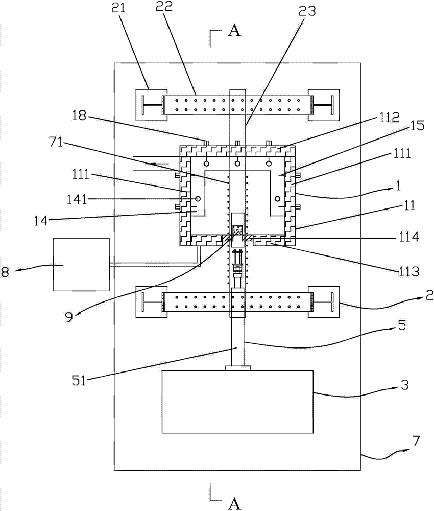
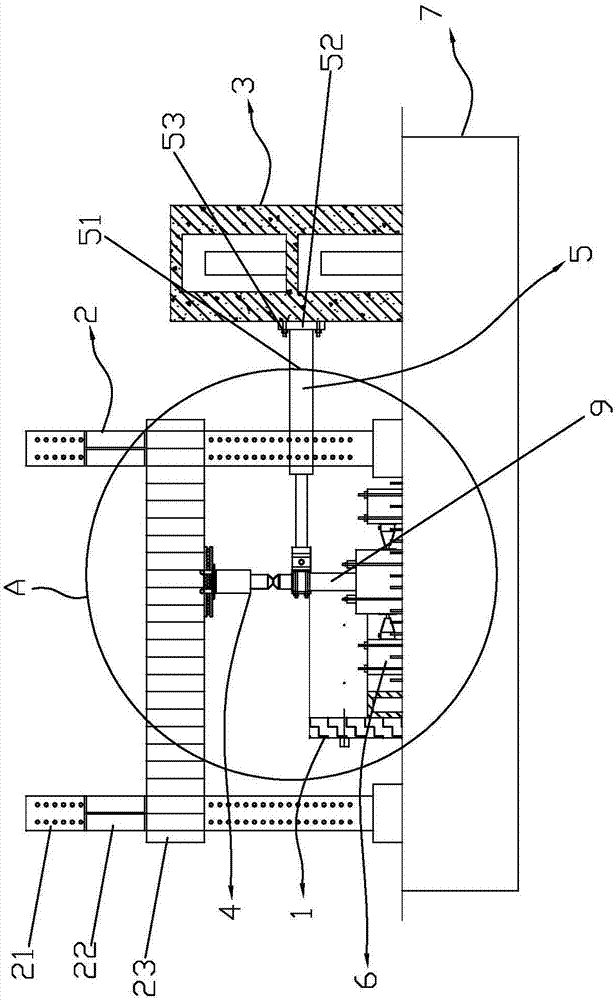
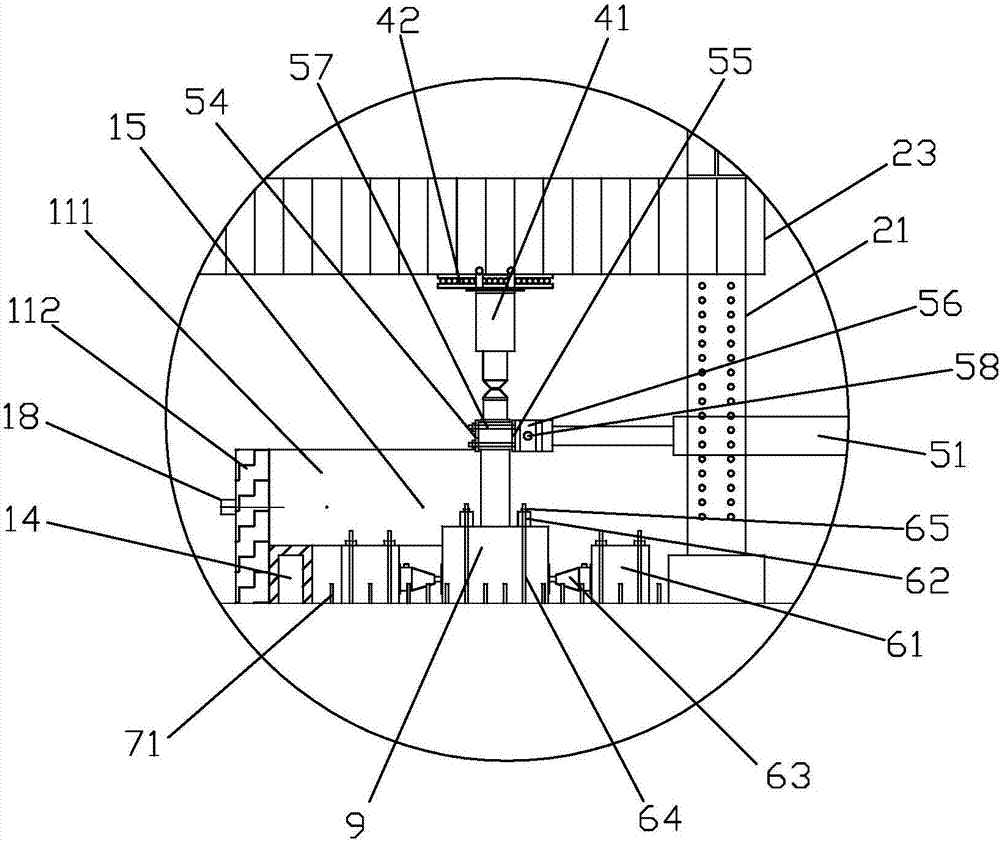
[0040] combine Figure 1 to Figure 6 , the quasi-static test device for non-surrounded concrete columns after fire in this embodiment includes a furnace body 1, a vertical reaction frame 2, a horizontal reaction wall 3, a vertical load loading device 4, a horizontal tension and compression servo loading device 5, Fixtures 6 , base platform 7 , data acquisition system and control center 8 . The basic platform 7 is used as the foundation of the furnace body 1, the vertical reaction frame 2, the horizontal reaction wall 3 and the fixing device 6. The vertical reaction frame 2 is composed of four steel columns 21, two longitudinal steel beams 22, and a middle horizontal steel beam 23. There are 2 rows of 18 ground anchors 71 pre-buried on the foundation platform 7, and the vertical distance between adjacent ground anchors 71 is 600 mm, and the horizont...


PUM


Abstract

The invention provides a pseudo-static testing device for concrete columns after non-peripheral fire exposure and an implementation method thereof. According to the fire exposure of a concrete column, two movable stove walls plus a temporary filling wall built in the middle opening are combined to form a fourth stove wall of a stove of the testing device. The stove is arranged in the body of a reaction frame, and a vertical load application unit is mounted on the bottom of a middle horizontal steel beam to apply vertical load on the concrete column; and a horizontal tension-compression servo loading unit is mounted on a horizontal reaction wall, and can apply pushover load and low-cycle horizontal reversed load on the concrete column specimen. The testing device first carries out a fire test under non-peripheral fire exposure on a loaded concrete column, and then carries out a pseudo-static test after fire extinguishment and cooling, and a data acquisition system is used for acquiring air pressure, temperature, displacement and load at each measuring point. The invention is applicable to the experimental study on the fire resistance and post-fire anti-seismic performance of concrete columns under non-peripheral (such as three-side, two-neighboring-sides and single-side) fire exposure.

Description

technical field [0001] The invention relates to the technical field of damage assessment of concrete structures after fire, in particular to a quasi-static test device and its implementation method that can consider various non-surrounding concrete columns after fire. Background technique [0002] Although the fire and high temperature will cause different degrees of damage to the mechanical properties of steel bars and concrete and the bonding and anchoring properties of the two, most reinforced concrete structures can still be used normally after damage assessment, reinforcement and repair, thereby exerting huge economic benefits. It is of great significance to scientifically and accurately evaluate the residual mechanical properties of reinforced concrete structures after fires, and to formulate repair and reinforcement plans for damaged structures to ensure the safety, applicability and durability of repaired structures after fires. . [0003] At present, some achieveme...

Claims


Application Information

Patent Timeline
IPC IPC(8): G01N3/02G01M7/02
CPCG01M7/02G01N3/02
Inventor 徐玉野董毓利胡小武罗漪王玲玲
Owner HUAQIAO UNIVERSITY
Why Eureka
Try Eureka