

Electrical cabinet heat radiation arrangement unit and control method thereof
A control method and technology for electrical cabinets, applied in the field of electrical cabinets, can solve the problems of reducing heat dissipation area, large fan vibration, large fan vibration, etc., and achieve the effects of increasing heat dissipation area, good heat dissipation effect and high safety.
- Summary
- Abstract
- Description
- Claims
- Application Information
AI Technical Summary
Problems solved by technology
Method used
Image

Examples
Embodiment 1
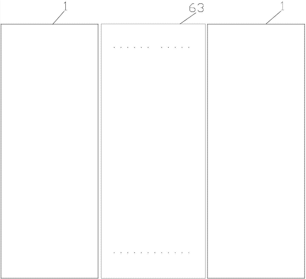
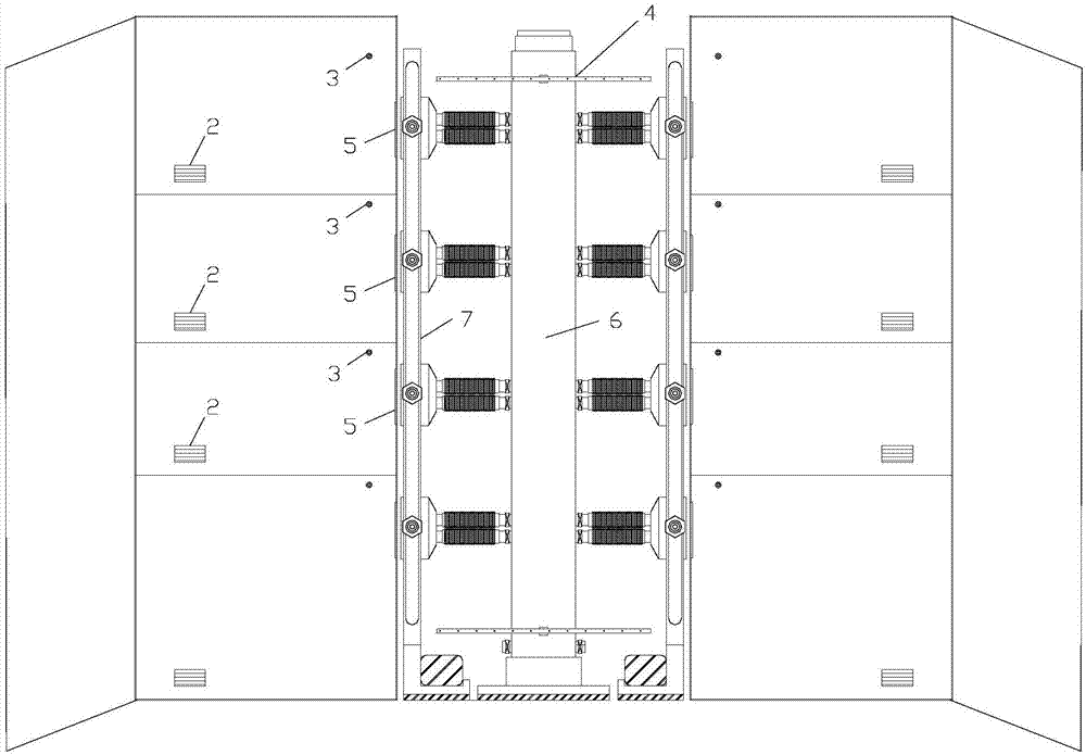
[0037] Such as figure 1 , 2 As shown, the heat dissipation arrangement unit of the electrical cabinet described in this embodiment includes two adjacent electrical cabinets 1, the electrical cabinets 1 are separated into a plurality of independent power distribution rooms, each power distribution room is equipped with A tuyere 2 and a temperature probe 3; it is characterized in that: a heat dissipation device 4 is provided between the two electrical cabinets 1, and a vent 5 is provided on the side of each power distribution room close to the heat dissipation device 4;
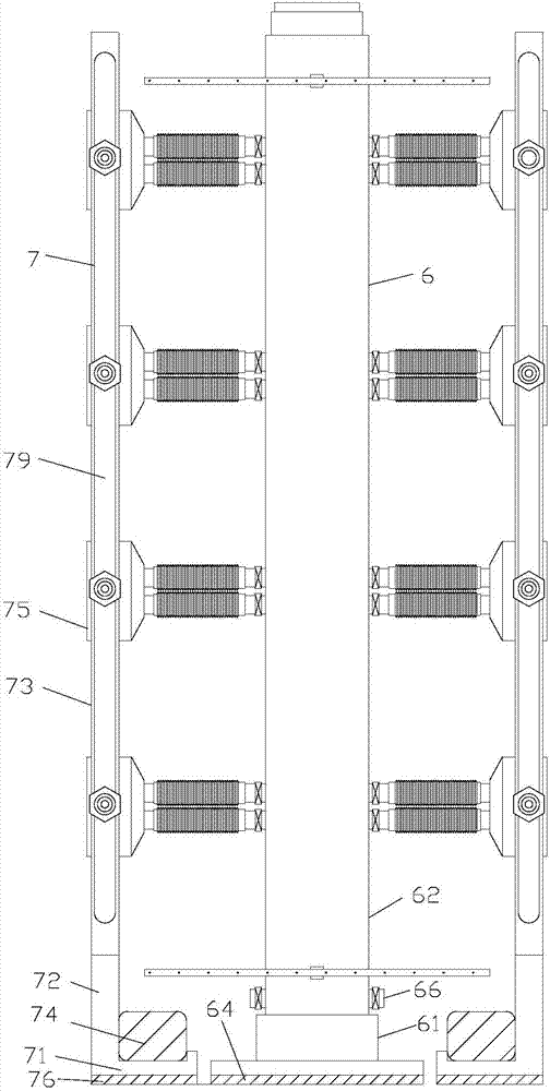
[0038] Such as image 3 As shown, the heat dissipation device 4 is composed of a draft device 6 in the middle and a draft rack 7 on both sides;
[0039] Such as Figure 4 , 5, the air extraction device 6 includes a base 61, an air chamber 62 and a cover plate 63; the air chamber 62 is arranged on the base 61, and the base 61 is provided with a cushion one 64 below the cushion one 64 Place it at the bottom t...
Embodiment 2
[0047] In the method for controlling the heat dissipation arrangement of the electric cabinet described in this embodiment, the heat dissipation arrangement unit of the electric cabinet described in the above embodiment 1 is controlled by the controller to control the operation of the motor of the fan 68; the difference from the embodiment 1 is that the control process is as follows:
[0048] In normal times, the fan 68 works once every TA (such as half an hour) (every time lasts 5-10 minutes). The air outlet pipe 66 at the lower part of the air cavity 62 is discharged, so that the hot air accumulated between the two electrical cabinets 1 flows and is discharged; at this time, since there is no power distribution room to draw air, all the air valves A and B are closed;
[0049] When the temperature of a power distribution room is higher than TL (but not higher than TH), the air valve A connected to the wind cover 75 corresponding to the power distribution room is opened, the a...
Embodiment 3
[0053] The difference between the method for controlling the heat dissipation arrangement of the electrical cabinet described in this embodiment and Embodiment 2 is that the speed VC of the fan 68 is controlled as follows:
[0054] VC= P*VM, P=(NA+NB) / NZ;
[0055] Wherein: VM is the maximum rotating speed of fan 68;
[0056] NA is the number of open dampers A;
[0057] NB is the number of open dampers B;
[0058] NZ is the total number of damper A and damper B;
[0059] When more valves are opened, the fan 68 works faster.
PUM
 Abstract
Description
Claims
Application Information