Quenching Furnaces for Vane Pump Rotors

A vane pump and quenching furnace technology, applied in the field of quenching furnace, can solve the problems of unreasonable, different preheating, incomplete austenitization, etc., and achieve the effect of making full use of energy and reducing waste

Inactive Publication Date: 2018-07-17
CHONGQING YONGCHUAN DISTRICT YIRUI MACHINERY
View PDF3 Cites 0 Cited by
  • Summary
  • Abstract
  • Description
  • Claims
  • Application Information

AI Technical Summary

Problems solved by technology

But there are still the following defects: 1. Due to the difference in the degree of preheating of the rotors of each vane pump, some products may be fully austenitized during the same heating time, and some products may be incompletely austenitized. The heating time of the pump rotor is unreasonable to judge whether the vane pump rotor is fully heated
2. After the parts are heated, it is necessary to turn on the discharge switch regularly, which is very troublesome

Method used


Image

  • Quenching Furnaces for Vane Pump Rotors

Examples


Embodiment Construction

[0018] The present invention will be described in further detail below by means of specific embodiments:

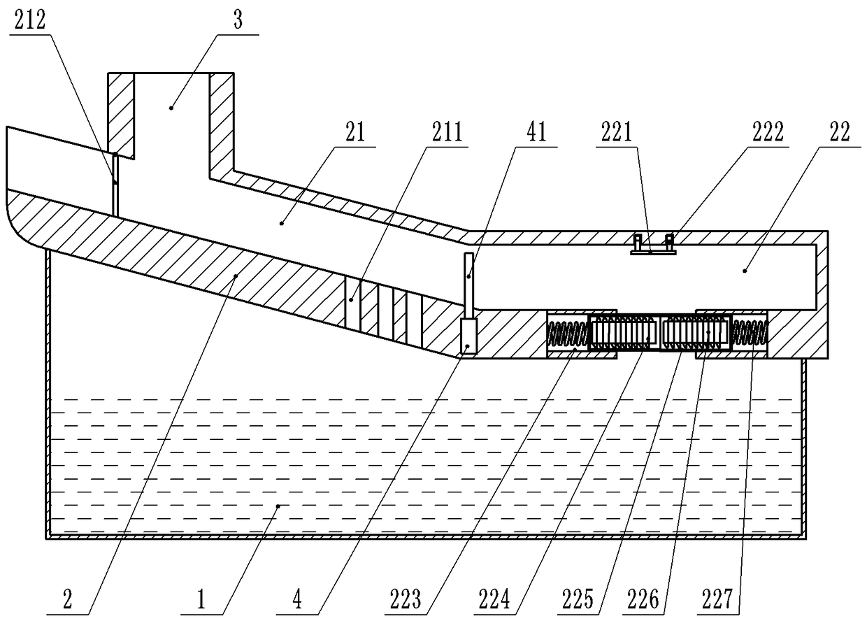
[0019] The reference signs in the drawings of the description include: oil pool 1, furnace body 2, preheating chute section 21, through hole 211, feed door 212, heating flat section 22, moving plate 221, telescopic rod 222, chute 223 , the first coil 224 , the slider 225 , the second coil 226 , the spring 227 , the exhaust port 3 , the cam 4 , and the separator 41 .

[0020] Such as figure 1 As shown, the quenching furnace for the vane pump rotor includes a furnace body 2, a quenching unit and a smoke exhaust unit. The furnace body 2 includes a preheating chute section 21 and a heating flat section 22 connected together, and the preheating chute section 21 A partition 41 is movably connected to the junction with the heating flat section 22 . The bottom of body of furnace 2 is provided with motor and the cam 4 that is used to drive partition 41 to move up and down, the o...


PUM


Abstract

The invention belongs to the technical field of heat treatment equipment, and particularly discloses a quenching furnace used for vane pump rotors. The quenching furnace comprises a furnace body, and the furnace body comprises a preheating chute section and a heating flat section; a discharging unit is arranged in the heating flat section and comprises springs, slide blocks, a first coil and a second coil; a discharging port and slide grooves are formed in the bottom of the heating flat section, and the slide blocks are connected on the slide grooves in a sliding mode; telescopic rods are fixed on the upper wall of the heating flat section, and a movable plate is fixed on the lower portions of the telescopic rods; one ends of the springs are connected on the slide blocks, and the other ends of the springs are connected on the slide grooves; and the first coil and the second coil are located in different slide blocks correspondingly, one end of the first coil is fixed on the upper wall in the heating flat section, the other end of the first coil is connected with the second coil, and the other end of the second coil is fixed on the upper surface of the movable plate. According to the quenching furnace used for the vane pump rotors, whether the vane pump rotors are heated sufficiently or not can be judged, and after the vane pump rotors are heated sufficiently, the discharging port opens automatically, so that the vane pump rotors fall into a quenching unit to be cooled.

Description

technical field [0001] The invention belongs to the technical field of heat treatment equipment, and in particular relates to a quenching furnace for a vane pump rotor. Background technique [0002] The vane pump is a pump in which the vanes in the rotor groove are in contact with the pump casing, and the sucked liquid is pressed from the oil inlet side to the oil discharge side. The pump is composed of components such as rotor, stator, vane, oil distribution plate and end cover. Before finishing the rotor of the vane pump, heat treatment such as quenching is required for the rotor. Quenching is to heat the product to a certain temperature, preheat it for a period of time, and then heat it above the critical temperature and keep it warm for a period of time to make all or part of the product austenitic. It is a heat treatment process in which martensite (or bainite) transformation is carried out by rapidly cooling below Ms (or isothermal near Ms) at a cooling rate greater t...

Claims


Application Information

Patent Timeline
Patent Type & Authority Patents(China)
IPC IPC(8): C21D9/00
CPCC21D9/0062C21D9/0068
Inventor 王文革
Owner CHONGQING YONGCHUAN DISTRICT YIRUI MACHINERY
Why Eureka
Try Eureka