Beam structure and drilling rig

A beam and drilling rig technology, which is applied to earth-moving drilling, wellbore/well components, etc., can solve the problems of unfavorable lightweight design of the upper beam structure of the outer arm, weak rigidity and strength of the upper beam of the outer arm, and heavy weight of the upper beam structure. , to achieve the effect of lightweight design, reasonable stiffness and strength matching, and light weight

Active Publication Date: 2020-03-24
JIANGSU XCMG STATE KEY LAB TECH CO LTD
View PDF6 Cites 0 Cited by
  • Summary
  • Abstract
  • Description
  • Claims
  • Application Information

AI Technical Summary

Problems solved by technology

[0004] The inventors have found that at least the following problems exist in the prior art: due to the unreasonable design of the upper beam structure of the outer arm of the existing vehicle-mounted deep well drilling rig, the rigidity and strength of the upper beam of the outer arm are relatively weak, causing the vehicle-mounted deep well drilling rig to twist during actual operation. The deformation is large, and the weld seam is easy to tear, which affects the stability of the whole vehicle; in order to increase its rigidity and strength, the method of increasing the size and thickness of the plate is used in the prior art, but the weight of the upper beam structure is large after the structural size is strengthened, which is not conducive to the exterior Lightweight design of beam structure on arm

Method used


Image

  • Beam structure and drilling rig
  • Beam structure and drilling rig
  • Beam structure and drilling rig

Examples


Embodiment Construction

[0030] Combine below Figure 1 to Figure 7 The technical solution provided by the present invention is described in more detail.

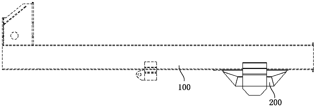
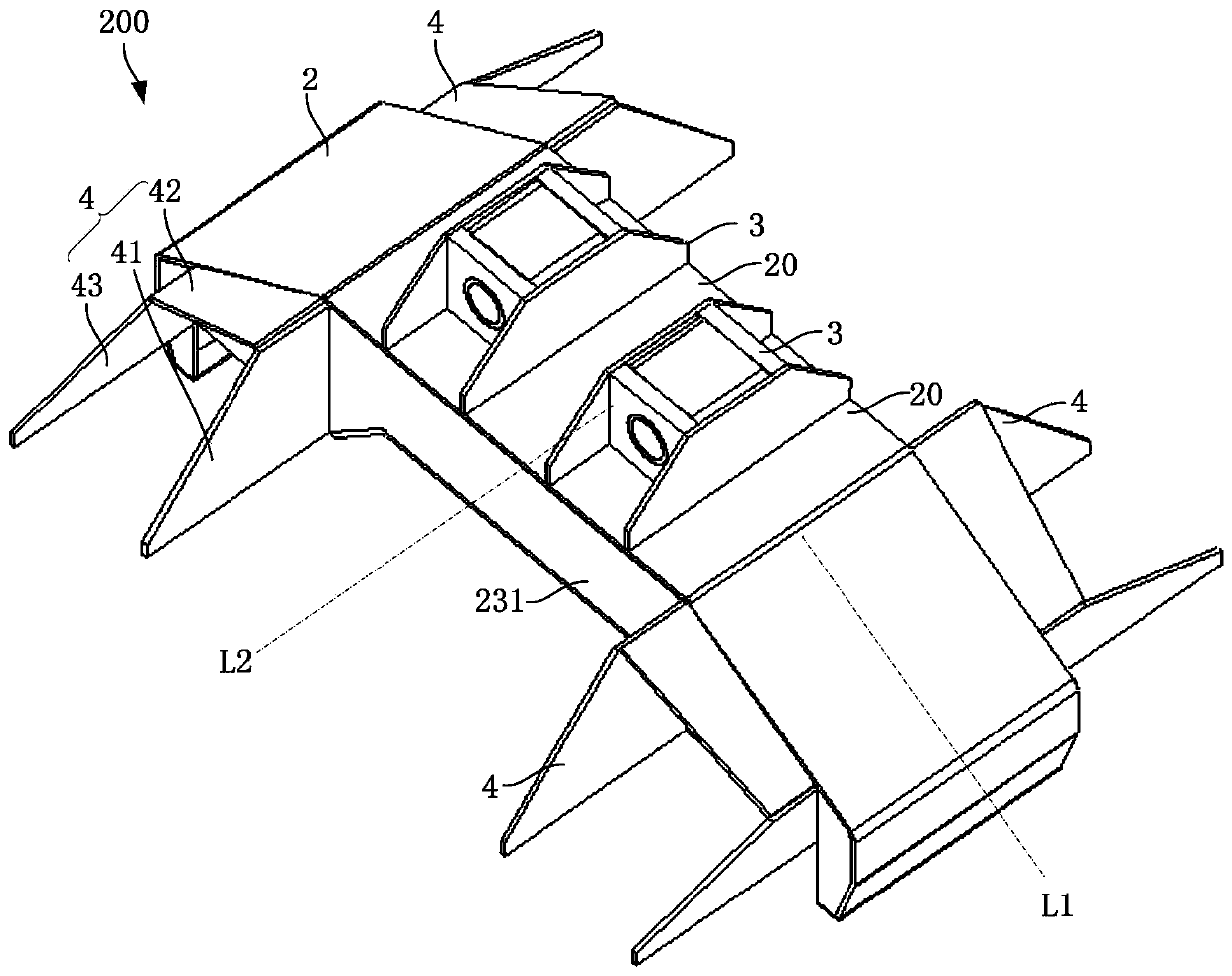
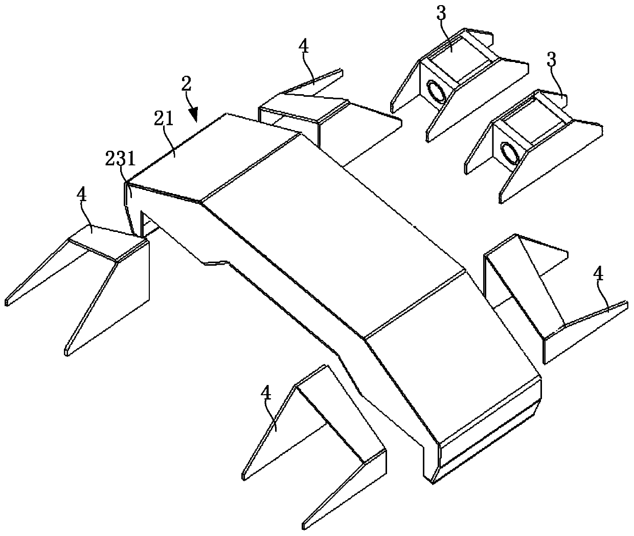
[0031] see figure 1 , the embodiment of the present invention provides a beam structure 200 for installation on the outer arm 100 of the drilling rig. The outer arm 100 of the drilling rig can be provided with a plurality of beam structures, and the beam structure 200 provided by the embodiment of the present invention is especially suitable as an upper beam structure, which is arranged on the middle and upper part of the outer wall 1 of the drilling rig. see figure 2 , the beam structure 200 includes a mounting portion 2 and a force receiving portion 3 , the mounting portion 2 is configured to protrude toward a direction away from the outer arm 100 of the drilling rig, and the force receiving portion 3 is mounted on the raised surface 20 of the mounting portion 2 .

[0032] The mounting part 2 is protruding, specifically, it may be an arched p...


PUM


Abstract

The invention discloses a cross-beam structure and a drilling machine, and relates to the field of engineering machinery. The cross-beam structure and the drilling machine are used for optimizing the cross-beam structure, and on the premise that the bearing capacity of the cross-beam structure is ensured, the lightweight of the cross-beam structure is achieved. The cross-beam structure is used for being installed at an external arm of the drilling machine and comprises an installation part and a stress part, the installation part is constructed to protrude towards the direction which is far away from the external arm of the drilling machine, and the stress part is installed on the protruding surface of the installation part. The cross-beam structure provided by the technical scheme comprises the protruding installation part and the stress part arranged on the protruding surface of the installation part, compared with an existing cross-beam structure, under the condition that the bearing capacities are the same, the cross-beam structure provided by the embodiment is lowest in weight, and the lightweight of the cross-beam structure can be achieved.

Description

technical field [0001] The invention relates to the field of engineering machinery, in particular to a beam structure and a drilling rig. Background technique [0002] Due to its strong mobility and convenient transition, vehicle-mounted deep well drilling rigs have become more and more widely used in the development of natural gas, coalbed methane, shale gas and other energy sources in recent years. The drilling tower structure of the vehicle-mounted deep well drilling rig is used for tension, compression and torsional loads, and is subjected to complex forces. The upper beam structure of the outer arm is an important component of the drilling tower structure and is the direct carrier for the lifting and lowering of the drilling tower. Since the upper beam of the outer arm is not located in the center of the outer arm after being loaded when the drilling tower is lifted and lowered, it will bear the bending moment. During drilling operations, the drilling tower is subjecte...

Claims


Application Information

Patent Timeline
Patent Type & Authority Patents(China)
IPC IPC(8): E21B41/00
CPCE21B41/0021
Inventor 陆永能高乐
Owner JIANGSU XCMG STATE KEY LAB TECH CO LTD
Why Eureka
Try Eureka