Inclined disc type Stirling engine

A Stirling engine and swash plate technology, applied in hot gas variable displacement engine devices, machines/engines, mechanical equipment, etc., can solve the complex structure of the swash plate, which affects the normal use of the Stirling engine, and the sealing structure of the piston rod Larger damage and other problems, to achieve the effect of simple structure, low cost, convenient processing, installation and disassembly

Inactive Publication Date: 2017-09-19
NANJING UNIV OF AERONAUTICS & ASTRONAUTICS
View PDF1 Cites 5 Cited by
  • Summary
  • Abstract
  • Description
  • Claims
  • Application Information

AI Technical Summary

Problems solved by technology

[0005] Although the swash plate structure has the above-mentioned advantages, the swash plate structure in the prior art is still too complicated, and it is necessary to add an additional guide post 1-3 to each piston 1-12 to reduce the force given to the swash plate 1 during the rotational movement of the main shaft 1-5. -7 and the circumferential reaction force of the piston rod 1-11 reduce the interaction force between the piston rod 1-11 and the cylinder, thereby reducing the friction between the piston 1-12 and the cylinder, so as not to affect the airtightness of the cylinder and cause damage
The search found the invention patent (Stirling engine swash plate transmission, 201310112466.6). Although the invention patent does not have the guide column 1-3, it completely relies on the interaction between the cylinder body and the piston rod 1-11 to offset the main shaft 1- 5. The circumferential reaction force given to the piston rod 1-11 during the rotation movement will cause great damage to the piston rod 1-11 and the sealing structure, and long-term use may affect the normal use of the Stirling engine

Method used


Image

  • Inclined disc type Stirling engine
  • Inclined disc type Stirling engine
  • Inclined disc type Stirling engine

Examples


Embodiment

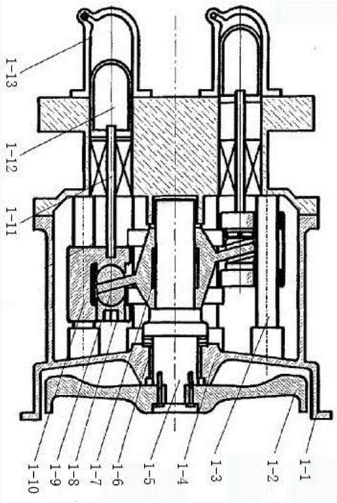
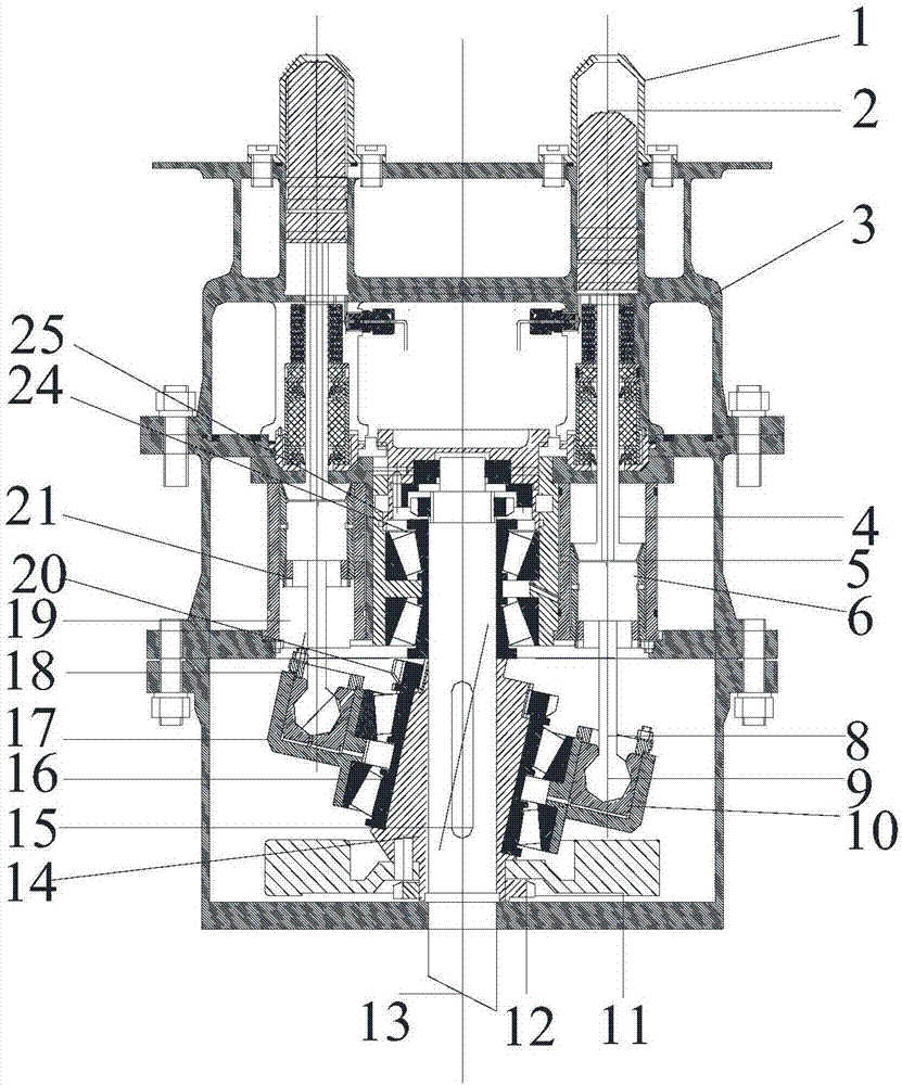
[0029] Such as figure 2 Shown, a kind of swash plate type Stirling engine comprises engine casing 3, cylinder 1, piston 2, piston rod 4, output main shaft 13 and swash plate transmission device, and this swash plate transmission device is used for piston 2 The linear motion is converted into a rotary motion of the output spindle 13 . The Stirling engine consists of four double-acting piston systems and their matching cylinders 1, which are all installed in the engine casing, and the cooler and regenerator connected to it are not connected to the swash plate transmission. The swash plate transmission includes a slide tube 19 and a swash plate mechanism, and one end of the piston rod 4 is shaped on a slide block 5, and the slide block 5 can move up and down in the slide tube 19.

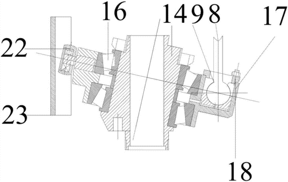
[0030] The swash plate mechanism includes a swash plate 17 and a slant sleeve 14 sleeved on the output spindle 13. The swash plate 17 is mounted on the outer circumference of the slant sleeve 14 thro...


PUM


Abstract

The invention relates to a Stirling engine, and belongs to the technical field of hot air engine utilization. The inclined disc type Stirling engine comprises an engine shell, an air cylinder, a piston, a piston rod, an output spindle and an inclined disc transmission device used for converting liner motion of the piston into rotation motion of the output spindle; the inclined disc transmission device comprises a sliding cylinder and an inclined disc mechanism; a sliding block is arranged at one end of the piston rod, and can vertically move in the sliding cylinder, the inclined disc mechanism comprises an inclined disc and an inclined shaft sleeve arranged on the output spindle in a sleeving manner, the inclined disc is arranged on the inclined shaft sleeve through a bearing, and the center line of the inclined shaft sleeve and the center line of the output spindle are crossed to form an included angle from 10 degrees to 15 degrees. The piston rod is not directly connected with the inclined disc, the piston rod is free of circumferential action force generated by rotation of the output spindle, the engine enables an output transmission device to be simpler only through one bearing, friction losses of the air cylinder and the piston can be reduced, and the service life can be prolonged.

Description

technical field [0001] The invention relates to a Stirling engine and belongs to the technical field of heat engine utilization. Background technique [0002] The Stirling Engine is an externally heated closed-cycle piston engine. In this type of machine, the working medium (generally hydrogen, helium or air) is enclosed in the circulation loop, and the flow direction of the working medium in the closed circulation loop is controlled by the variable ratio of the cylinder volume; at lower temperatures and The working fluid is compressed under pressure and expanded under higher temperature and pressure to obtain positive cycle work. Its thermodynamic process is carried out according to the Stirling cycle. [0003] The double-acting Stirling engine is generally composed of four cylinders, four coolers and regenerators connected in a certain sequence of hot and cold structures. The high-pressure gas working medium is heated and expanded on the upper part of the cylinder, driv...

Claims


Application Information

Patent Timeline
Patent Type & Authority Applications(China)
IPC IPC(8): F02G1/043F02G1/053
CPCF02G1/043F02G1/053
Inventor 黄护林朱桂平
Owner NANJING UNIV OF AERONAUTICS & ASTRONAUTICS
Why Eureka
Try Eureka