
Method for detecting the position of oblique holes in parts

A detection method and technology for parts, which are applied to measurement devices, optical devices, instruments, etc., can solve the problems of long production cycle, high cost, and high calibration technical requirements, and achieve the effects of cost saving, design reduction, and high detection accuracy.

Active Publication Date: 2019-07-16
DALIAN SANYO COMPRESSOR
View PDF5 Cites 0 Cited by
  • Summary
  • Abstract
  • Description
  • Claims
  • Application Information

AI Technical Summary

Problems solved by technology

[0004] According to the above-mentioned technical problems, a method for detecting the position of oblique holes in parts is provided, which is used to solve the problem of the existing measuring instruments dedicated to the positions of oblique holes in parts, which have high cost, long production cycle, and high technical requirements for daily maintenance and calibration. Disadvantages of parts inspection not suitable for product development stage, trial production stage and small batch production stage

Method used


Image

  • Method for detecting the position of oblique holes in parts
  • Method for detecting the position of oblique holes in parts
  • Method for detecting the position of oblique holes in parts

Examples


Embodiment Construction

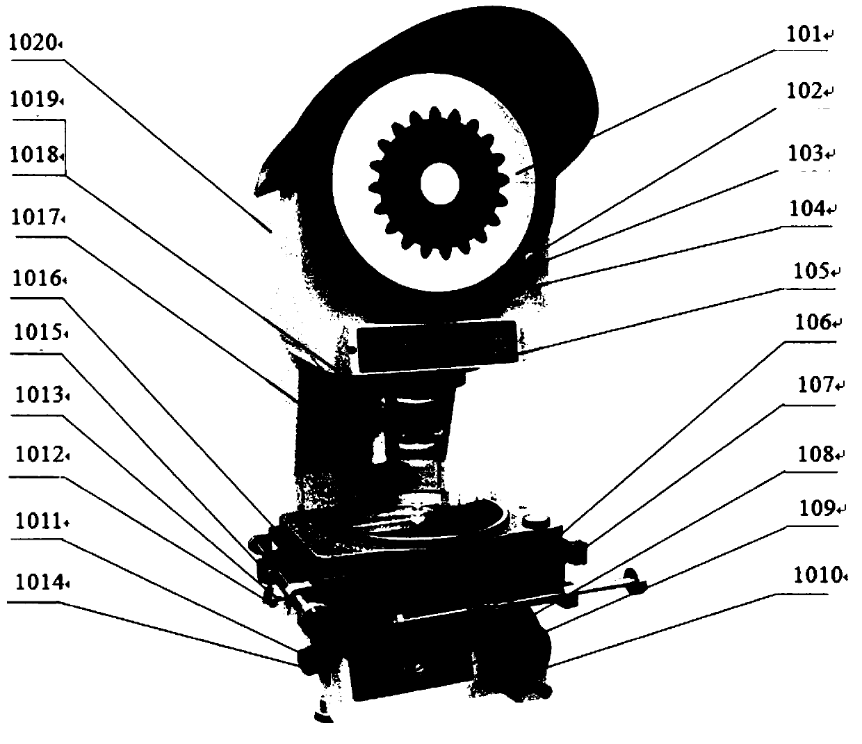
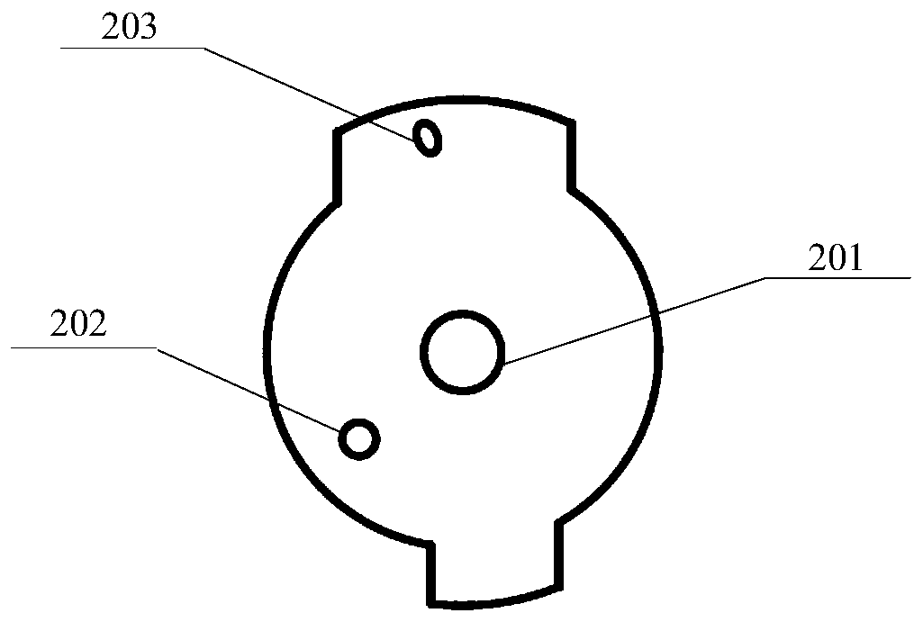
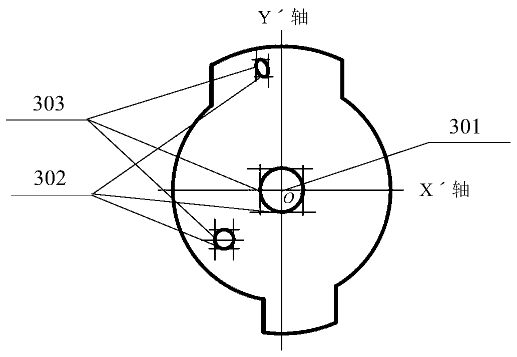
[0051] Such as Figure 1 to Figure 8 As shown, a method for detecting the position of oblique holes in parts includes the following detection steps:

[0052] S1. Using a measuring projector to establish a detection coordinate system (Xˊ, Yˊ) on the projection screen based on the center hole A of the component; S1 specifically includes the following steps:

[0053] S11. Place the part with the side of the oblique hole facing up on the center of the workbench 1016 of the measuring projector, turn on the power switch 107 of the measuring projector, turn the lifting hand wheel 1010 of the projection box to adjust the focus to the upper surface of the part, Until the central hole A201 of the component is clearly projected on the projection screen 101 of the measuring projector.

[0054] S12. Rotate the horizontal axis and vertical axis handwheels on the measuring projector workbench 1016 respectively to confirm that the contours of the central hole A201, positioning hole B202 and ...


PUM


Abstract

The invention discloses a method for detecting the position of an inclined hole of a part, and the method comprises the following steps: S1, building a detection coordinate system (X', Y') on a projection screen through a measurement projector, wherein a central hole A of the part is taken as the reference; S2, detecting the coordinate values of the position of a positioning hole B and the position of an inclined hole C on the projection screen of the measurement projector according to the relative position of the positioning hole B and inclined hole C with the central hole A; S3, building a theoretical coordinate system (X, Y) at a drawing interface through AutoCAD, drawing the coordinates, detected by the measurement projector, of the positioning hole B and inclined hole C of the part in an AutoCAD theoretical coordinate system, and correcting the coordinates. The method provided by the invention can achieve the detection of the size of the part, also can save cost for an enterprise, and is a flexible detection method for the position of the inclined hole of the part.

Description

technical field [0001] The invention relates to the technical field of industrial detection, in particular to a method for detecting the positions of oblique holes of parts by using a digital measuring projector and AutoCAD drawing software. Background technique [0002] In the existing industrial testing field, there are two ways to detect the position of the oblique hole of the parts. One is to use a special measuring instrument, which is convenient and fast to operate and is suitable for mass production; the other is to use general testing equipment such as three coordinates, which is suitable for Trial production and small batch production. [0003] The shortcomings of the existing technology are: the general design cost of the special measuring instrument for the oblique hole position of the parts is high, the production cycle is long, and the technical requirements for daily maintenance and calibration are high, so it is not suitable for parts in the product developmen...

Claims


Application Information

Patent Timeline
Patent Type & Authority Patents(China)
IPC IPC(8): G01B11/00
CPCG01B11/00
Inventor 徐志辉曲洪伟沙超
Owner DALIAN SANYO COMPRESSOR
Learn More