
Wiring terminal

A technology of connecting terminals and connecting bodies, applied in the direction of connection, conductive connection, clamping/spring connection, etc., can solve the problems of troublesome users, complex structure, and difficulty in functioning, and achieve reduced production costs, easy manufacturing, and simple structure Effect

Pending Publication Date: 2017-09-19
GUANGZHOU GOLD ELECTRIC LIGHTING
View PDF4 Cites 0 Cited by
  • Summary
  • Abstract
  • Description
  • Claims
  • Application Information

AI Technical Summary

Problems solved by technology

However, for the current terminal field, when the wire is inserted into the terminal, although the wire head can rotate in the terminal, it is difficult for the wire to be pulled out due to the occlusion of the metal sheet.
Therefore, when each interconnected wire needs to be disconnected (for example, when an LED lamp needs to be replaced), the user generally can only directly cut off the end of the wire. , and cause a huge waste of resources
[0004] For this reason, someone sets an off-line button on the terminal, and pushes the metal sheet away by pressing the off-line button, so that the wire is loosened, but the structure is complicated, which increases the cost of parts and also increases the difficulty of assembly
Some people also open a through hole on the housing of the terminal block, and then use an appropriate tool (such as a thimble) to insert into the housing to push the metal sheet away, so that the wires can be loosened. Although this structure is simple, it requires additional tools. , it is still more troublesome for users

Method used


Image

  • Wiring terminal
  • Wiring terminal
  • Wiring terminal

Examples


Embodiment 1

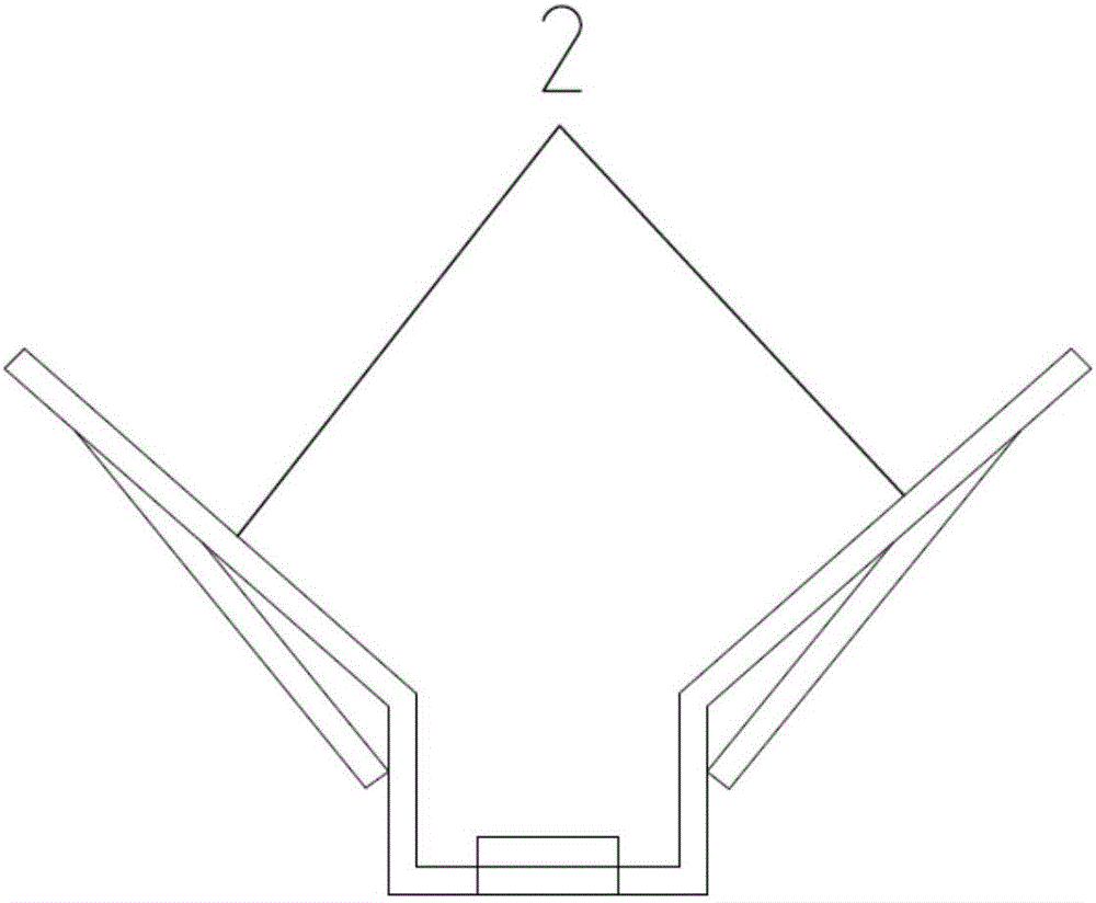
[0046] This embodiment discloses a connection terminal, such as Figure 1-8 As shown in , 13, it includes a shell 1 provided with a hollow portion 11, and two or more wiring bodies 2 that can be electrically connected to each other.

[0047] Such as Figure 6-8, 13, the casing 1 is provided with more than two first through holes 12 for the external wires 3 to pass through; a plurality of wiring bodies 2 are located in the hollow portion 11 of the casing 1; each wiring body 2 and each first through hole 12 are connected in one-to-one correspondence, so that the external wire 3 can pass through the first through hole 12 and make good contact with the wiring body 2 to realize the conductive function.

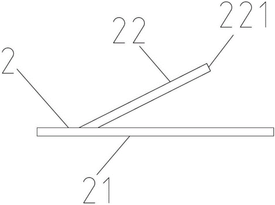
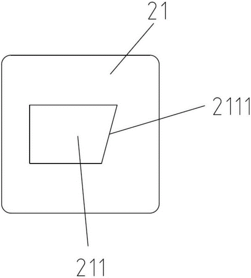
[0048] Such as figure 1 , 2 As shown, each wiring body 2 includes a supporting surface 21 and an elastic portion 22 . The supporting surface 21 is provided with a second through hole 211 with edges. In this embodiment, for the convenience of production, the elastic part 22 and ...

Embodiment 2

[0057] This embodiment discloses another connection terminal, the key differences in structure from the connection terminal described in Embodiment 1 are:

[0058] Such as Figures 9 to 12 As shown, the number of connecting pieces 4 is 2, and each connecting piece 4 includes a hooked portion 41 and a conductive connecting portion 42 connected to the hooked portion 41; the cover body 5 is provided with 6 first through holes 12, The second end 14 is provided with two first through holes 12; the six wiring bodies 2 corresponding to the six first through holes 12 on the cover body 5 are integrally formed with a fourth through hole 24 and a fifth through hole therebetween. hole 25; the conductive connection parts 42 of the two connecting pieces 4 pass through the fourth through hole 24 and the fifth through hole 25 respectively and respectively withstand the wiring body 2 corresponding to the two first through holes 12 on the second end 14, And each hook portion 42 hooks the wirin...


PUM

PropertyMeasurementUnit
Bevel angleaaaaaaaaaa

Abstract

The invention discloses a wiring terminal, and the wiring terminal comprises a housing with a hollow part, and two or more wiring bodies which can be electrically connected with each other. The housing is provided with two or more first through holes for allowing external wires to pass. Each wiring body is located in the hollow part of the housing. Each wiring body is correspondingly connected with the corresponding first through hole. Each wiring body comprises a supporting face and an elastic part. Each supporting face is provided with a second through hole, and each elastic part is disposed at the mouth of a second through hole and is warped. The elastic parts are provided with holding-on edges, and the holding-on edges are inclined, so as to enable the heads of the external wires to enter the second through hole and to be tightly set in a region between the second through hole and the holding-on edges and to rotate in the inclination direction of the holding-on edges so as to escape from the region. The wiring terminal can achieve the quick and convenient connection or disconnection of a plurality of wires, can achieve the disconnection of wires without cutting, and effectively saves the utilization amount of wires.

Description

technical field [0001] The invention belongs to the technical field of electrical connection accessories, and in particular relates to a connection terminal. Background technique [0002] Terminal block is an accessory product used to realize electrical connection, which is industrially divided into the category of connectors. With the development of the electronics industry, the use of terminal blocks is increasing, and there are more and more types. At present, it is most widely used in the production and use of LED products. [0003] The terminal block is actually a section of interconnected metal sheets sealed in insulating plastic. Through the insulating plastic, there are through holes through which the wires can be inserted so that the wires can be in contact with the metal sheets, and the elastic metal sheets are used for occlusal connection. This facilitates the connection of multiple wires. However, for the current connection terminal field, after the wire is in...

Claims


Application Information

Patent Timeline
IPC IPC(8): H01R9/24H01R4/48
CPCH01R9/24H01R4/48365
Inventor 林闽应
Owner GUANGZHOU GOLD ELECTRIC LIGHTING
Learn More