
Inverter drive device and semiconductor module

A drive device and inverter technology, which is applied to output power conversion devices, AC motor control, and AC power input conversion to DC power output, etc. problem, to achieve the effect of preventing overvoltage damage and preventing overvoltage breakdown

Active Publication Date: 2017-09-19
FUJI ELECTRIC CO LTD
View PDF5 Cites 8 Cited by
  • Summary
  • Abstract
  • Description
  • Claims
  • Application Information

AI Technical Summary

Problems solved by technology

[0025] In this way, if the internal impedance of the upper arm drive circuit 6 (6u, 6v, 6w) is increased, the switching loss in the upper arm IGBT 2u (2v, 2w) will increase when the inverter 10 is operating normally.
In addition, as the heat generated by the conduction operation of the upper arm IGBT 2u (2v, 2w) increases, the switching operation becomes difficult when the general switching frequency of the inverter 10 is 10 Hz or higher.

Method used


Image

  • Inverter drive device and semiconductor module
  • Inverter drive device and semiconductor module
  • Inverter drive device and semiconductor module

Examples


Embodiment Construction

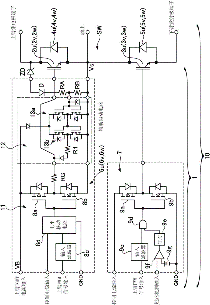
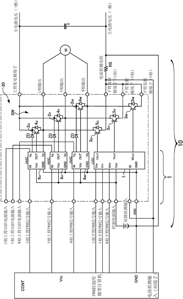
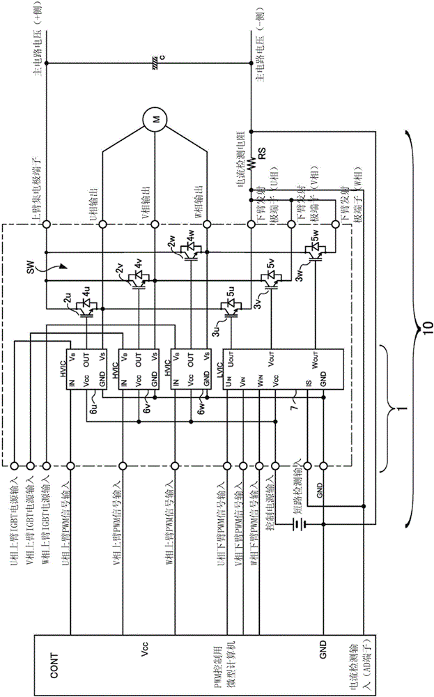
[0066] Hereinafter, an inverter driving device according to an embodiment of the present invention will be described with reference to the drawings, taking a U-phase inverter driving device for driving a three-phase motor as an example. Additionally, for image 3 as well as Figure 4 The same symbols are used for the same parts of the conventional devices shown, and description thereof will be omitted. In addition, among the inverters for driving a three-phase motor, the V-phase and W-phase inverter drive devices are also configured in the same manner as the U-phase inverter drive device described here.

[0067] The inverter driving device 1 according to one embodiment of the present invention, as in figure 1 A schematic configuration thereof is shown in , which includes a main drive circuit 11 that applies a drive voltage to a semiconductor switching element SW provided at the output stage of the inverter 10 to control the current output to the load, thereby turning the sem...


PUM


Abstract

The invention provides an inverter drive device capable of suppressing loss of a semiconductor switching element arranged at an output stage and controlling an output current output to a load during normal operation and preventing overvoltage damage to the semiconductor switching element in an abnormal state. The inverter drive device includes a main drive circuit configured to apply a drive voltage to the semiconductor switching element (such as an IGBT), to thereby turn on and off the semiconductor switching element, a clamping diode configured to clamp a voltage of a counter electromotive force applied to the semiconductor switching element during operation stop of the main drive circuit, a voltage dividing resistor configured to perform resistance voltage dividing and detect a voltage that is proportional to a current flowing through the clamping diode, and an auxiliary drive circuit configured to generate a control voltage in accordance with the voltage detected by the voltage dividing resistor, and to apply the control voltage to the semiconductor switching element, to thereby turn on the semiconductor switching element.

Description

technical field [0001] The present invention relates to an inverter driving device provided at an output stage of an inverter to turn on and off a semiconductor switching element that controls a current output to a load, and an inverter driving device integrally equipped with the inverter driving device and A semiconductor module of the semiconductor switching element. Background technique [0002] The inverter 10 for driving a single-phase motor or a three-phase motor has a semiconductor switching element SW for controlling the current output to the load at its output stage, and an inverter for turning the semiconductor switching element SW on and off. drive unit 1. image 3 It is a diagram showing a schematic configuration of an inverter 10 that drives a three-phase motor M as a load. As a semiconductor switching element SW, an upper arm that is connected to a U-phase, a V-phase, and a W-phase in a totem-pole manner and is driven to conduct in a complementary manner is pro...

Claims


Application Information

Patent Timeline
Patent Type & Authority Applications(China)
IPC IPC(8): H02M7/5387H02M7/5395
CPCH02M7/53873H02M7/5395H02M1/08H02M1/32H02M7/5387H02P27/08H02M1/0009H02M1/344
Inventor 山田忠则
Owner FUJI ELECTRIC CO LTD
Learn More