
Control method and system of permanent magnet synchronous motor

A technology of permanent magnet synchronous motor and control method, which is applied in the direction of control system, vector control system, motor generator control, etc., can solve the problem of motor current limitation and protection, the motor stator current cannot be directly controlled, and the mathematical expression of permanent magnet synchronous motor complicated formula

Active Publication Date: 2017-09-19
CSR ZHUZHOU ELECTRIC LOCOMOTIVE RES INST
View PDF7 Cites 7 Cited by
  • Summary
  • Abstract
  • Description
  • Claims
  • Application Information

AI Technical Summary

Problems solved by technology

[0006] Third: The magnitude of the motor stator current cannot be directly controlled
Since the mathematical expressions of the stator flux and torque of the permanent magnet synchronous motor are very complicated, the given flux can only be obtained by curve fitting at present.
This method can reduce the problem that the motor current is too large under constant flux control, but in actual engineering applications, due to the error of motor parameters and the deviation of flux linkage observation, it is impossible to ensure that the actual current runs accurately according to the MTPA curve, so the adaptability poor
For the third problem, because the direct torque control strategy itself does not directly control the current, it cannot directly limit and protect the motor current like the vector control technology.
When the load is abnormally large, the motor current may exceed the limit value, and in severe cases, overcurrent may occur

Method used


Image

  • Control method and system of permanent magnet synchronous motor
  • Control method and system of permanent magnet synchronous motor
  • Control method and system of permanent magnet synchronous motor

Examples


Embodiment Construction

[0056] The core of the present invention is to provide a permanent magnet synchronous motor control method and system, which combines current control and direct torque control, realizes simultaneous control of torque and current, and solves all the shortcomings of the general direct torque control method.

[0057] In order to make the purpose, technical solutions and advantages of the embodiments of the present invention clearer, the technical solutions in the embodiments of the present invention will be clearly and completely described below in conjunction with the drawings in the embodiments of the present invention. Obviously, the described embodiments It is a part of embodiments of the present invention, but not all embodiments. Based on the embodiments of the present invention, all other embodiments obtained by persons of ordinary skill in the art without making creative efforts belong to the protection scope of the present invention.

[0058] This embodiment is not limit...


PUM


Abstract

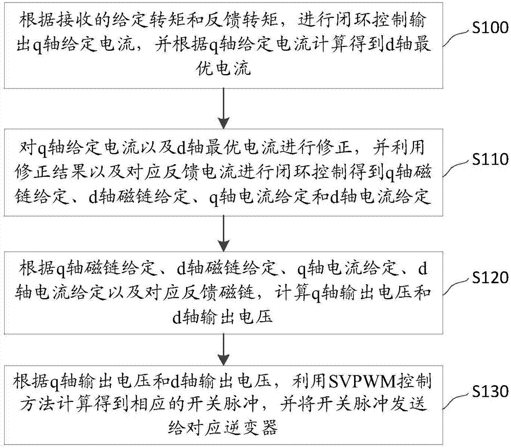
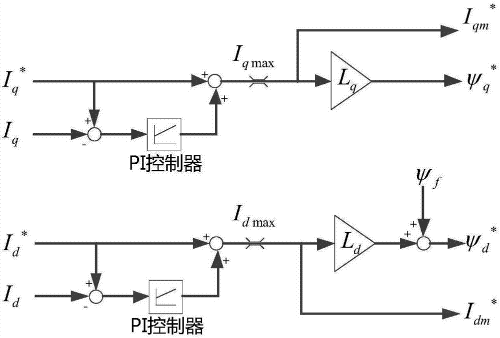
The present invention discloses a control method and a system of a permanent magnet synchronous motor. The method comprises the steps of conducting the closed-loop control and outputting a q-axis given current according to a received given torque and a feedback torque, and calculating to obtain a d-axis optimal current according to the q-axis given current; correcting the q-axis given current and the d-axis optimal current, and conducting the closed-loop control to obtain a q-axis given flux linkage, a d-axis given flux linkage, a q-axis given current and a d-axis given current based on the corrected q-axis given current, the corrected d-axis optimal current and a corresponding feedback current; according to the given flux linkages, the given currents and a corresponding feedback flux linkage, calculating a q-axis output voltage and a d-axis output voltage; according to the q-axis output voltage and the d-axis output voltage, calculating to obtain a corresponding switch pulse by using the SVPWM control method, and sending the switch pulse to a corresponding inverter. According to the technical scheme of the invention, the current control and direct torque control are combined together, so that the torque and the current are controlled at the same time. Therefore, all disadvantages during the conventional direct torque control method can be solved.

Description

technical field [0001] The invention relates to the technical field of motor control, in particular to a method and system for controlling a permanent magnet synchronous motor. Background technique [0002] The permanent magnet synchronous motor is a synchronous motor that is excited by a permanent magnet to generate a synchronous rotating magnetic field. The permanent magnet synchronous motor can install the motor on the wheel shaft as a whole to form an overall direct drive system, that is, a wheel shaft is a drive unit, eliminating the need for a gear. box. It has high power efficiency and high power factor; low heat generation, corresponding to a simple structure, small volume and low noise of the motor cooling system; large allowable overload current and significantly improved reliability; since there is no gearbox, the bogie system can be freely designed: Such as flexible bogies and single-axle bogies, which greatly improve the dynamic performance of trains, are widel...

Claims


Application Information

Patent Timeline
IPC IPC(8): H02P21/22H02P21/20H02P21/30
Inventor 冯江华许峻峰郑汉锋梅文庆刘勇文宇良张朝阳甘韦韦黄佳德曾小凡
Owner CSR ZHUZHOU ELECTRIC LOCOMOTIVE RES INST
Learn More