
Camera cover plate and camera

A camera and head cover technology, applied in image communication, optical filters, instruments for photography, etc., can solve the problems of affecting the shooting effect, loss of anti-fog, limited water absorption capacity of the hydrophilic film, etc., to ensure the camera effect, Guaranteed transparency

Pending Publication Date: 2017-09-19
TRULY OPTO ELECTRONICS
View PDF8 Cites 4 Cited by
  • Summary
  • Abstract
  • Description
  • Claims
  • Application Information

AI Technical Summary

Problems solved by technology

Although the hydrophilic film can play the role of anti-fog, the existence of the film layer seriously affects the light transmission of the camera cover, which not only affects the shooting effect, but also reduces the aesthetics of the camera; moreover, the water absorption capacity of the hydrophilic film is limited, When it reaches saturation, it loses the anti-fog effect and the use effect is not good

Method used


Image

  • Camera cover plate and camera

Examples


Embodiment Construction

[0021] The core of this specific embodiment is to provide a camera cover, which can ensure the light transmittance of the camera cover and at the same time play an anti-fog effect without affecting the overall appearance of the camera. field problems.

[0022] Hereinafter, an embodiment will be described with reference to the drawings. In addition, the examples shown below do not limit the content of the invention described in the claims in any way. In addition, all the contents of the configurations shown in the following embodiments are not limited to be essential to the solutions of the invention described in the claims.

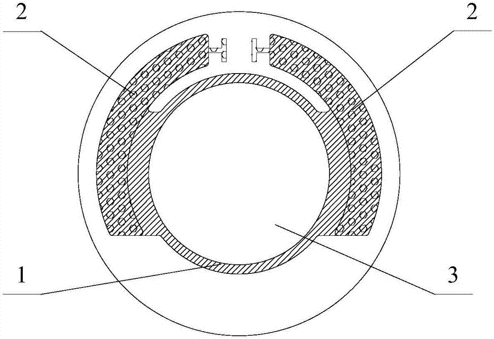
[0023] The camera cover plate provided in this specific embodiment may include an indium tin oxide layer 1 and two conductive layers 2; wherein, the indium tin oxide layer 1 and the two conductive layers 2 are all arranged on the non-imaging area of ​​the camera cover plate, and the two Each conductive layer 2 is in communication with the indium tin oxi...


PUM


Abstract

The present invention discloses a camera cover plate and a camera. The camera cover plate comprises an indium tin oxide layer and two conductive layers; the indium tin oxide layer is arranged in a non-image pick-up area of the camera cover plate; and the two conductive layers are arranged in the non-image pick-up area and are both communicated with the indium tin oxide layer. When the camera cover plate is used, a direct-current voltage is applied between the two conductive layers; since the conductive layers are communicated with the indium tin oxide layer, the indium tin oxide layer has an electrical conductivity characteristic and an optical transparency characteristic, after the voltage is applied, the indium tin oxide layer will be heated, and the temperature of the camera cover plate will rise, and therefore, an anti-fog effect can be realized, and the overall appearance of the camera will not be affected; and the indium tin oxide layer avoids an image pick-up area, and therefore, the light transmission performance of the camera cover plate will not be affected. Therefore, the light transmission performance of the camera cover plate provided by the present invention can be ensured, the camera cover plate can realize the anti-fog effect, the overall appearance of the camera will not be affected, and problems in the field at present can be solved.

Description

technical field [0001] The invention relates to the field of anti-fog, and more specifically, to a camera cover plate and a camera. Background technique [0002] The camera is the main component for smart devices to collect external information, so it is particularly important to keep a clear shooting effect at all times. However, in actual use, especially when the ambient temperature changes, the shooting effect is not satisfactory; for example, when the camera changes from a low-temperature environment to a relatively high-temperature environment, the camera cover will be fogged, which directly affects the shooting effect. [0003] In the prior art, for the phenomenon of fogging on the camera cover, it is mainly avoided by adding an anti-fog layer, that is, spraying a hydrophilic film on the camera cover; when fogging occurs, the fog beads will be absorbed by the hydrophilic film, So as to achieve the anti-fog effect. Although the hydrophilic film can play the role of an...

Claims


Application Information

Patent Timeline
Patent Type & Authority Applications(China)
IPC IPC(8): H04N5/225G03B11/04G03B30/00
CPCG03B11/04H04N23/50
Inventor 谢智威邱泽银周伟杰李志成李建华
Owner TRULY OPTO ELECTRONICS
Learn More