Anti-clogging reaction vessel

A reaction kettle and anti-clogging technology, which is applied in the direction of chemical/physical/physical chemical fixed reactor, filtration separation, fixed filter element filter, etc. Problems such as production and operation costs can be achieved by reducing extremely easy blockage, increasing sealing effect, and simple structure

Active Publication Date: 2017-09-22
HENGYANG YISHUN CHEM CO LTD
View PDF4 Cites 8 Cited by
  • Summary
  • Abstract
  • Description
  • Claims
  • Application Information

AI Technical Summary

Problems solved by technology

[0002] Reactor is a commonly used production equipment in the chemical industry. It generally includes a tank body, raw material inlets and product outlets installed on the tank body, control valves, and a circulating condensation separator installed on the top of the tank body; the inside of the tank body is equipped with an inlet Heating circulation device for hot steam or high-temperature heat-conducting oil; when putting in liquid materials of different viscosities and solid-liquid mixtures for synthesis reactions, there are usually motor-driven motors of different sizes and different stirring and homogenizing methods inside the tank At present, the reactor stirring homogenizers used in the chemical industry mainly include the following types: one is fixedly connected with a single horizontal blade stirring device on the stirring shaft; the other is fixedly connecting a single horizontal blade stirring device at the bottom of the stirring shaft Anchor-type slurry stirring device; the third is to fix the frame-type slurry stirring device at the lower part of the stirring shaft; the above-mentioned several agitators have different application advantages in different chemical synthesis processes, but they are suitable...

Method used


Image

  • Anti-clogging reaction vessel

Examples


Embodiment Construction

[0023] The technical solutions of the present invention will be described in detail below in conjunction with embodiments. The following examples are only used to illustrate the technical solutions of the present invention more clearly, and therefore are only examples, rather than limiting the protection scope of the present invention.

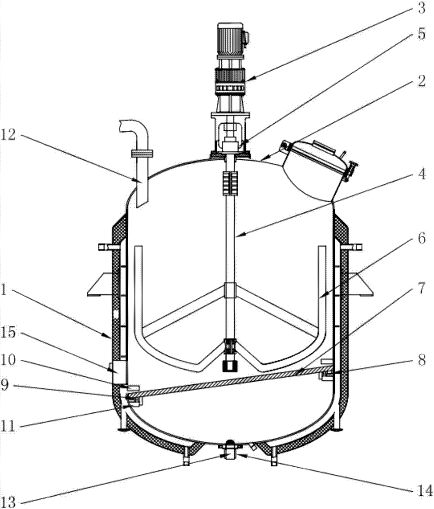
[0024] Such as figure 1 As shown, an anti-clogging reaction kettle includes a kettle body 1, a kettle cover 2 is installed on the top of the kettle body 1, and a stirring mechanism is installed on the kettle cover 2. The stirring mechanism includes a power part 3, a stirring shaft 4 and a shaft seal part 5. One end of the stirring shaft 4 is power-installed with the power part 3, and the other end of the stirring shaft 4 passes through the kettle cover 2 and extends into the interior of the kettle body 1, and the stirring shaft 4 placed inside the kettle body 1 is equipped with a stirring blade 6 , the stirring shaft 4 is equipped with a shaf...


PUM


Abstract

The invention relates to the field of a chemical industrial device, specifically to an anti-clogging reaction vessel. The reaction vessel includes a vessel body; a cover is mounted on the top of the vessel; a stirring mechanism is mounted on the cover; a filter screen adapted to a cross-section of the vessel body is mounted at the lower part of a stirring shaft; a gravity inductor is mounted at an edge of the filter screen; a vibrating component is arranged at the lower part of the gravity inductor and comprises a mounting base and a vibrator, which is internally provided with a circuit board, wherein the circuit board is in electrical connection to the gravity inductor; and the lower part of the vessel body is provided with a discharge port, which is provided with a hemispheric filtering blocking screen and is covered with a heating belt. The vessel is simple in structure and convenient to operate, prevents the phenomenon of super difficult movement of materials in the vessel, reduces large blocks in the materials, and can prevent the phenomenon that the discharge port is clogged due to temperature variation.

Description

technical field [0001] The invention relates to the field of chemical equipment, in particular to an anti-clogging reaction kettle. Background technique [0002] The reaction kettle is a commonly used production equipment in the chemical industry. It generally includes a tank body, a raw material inlet, a product outlet, a control valve installed on the tank body, and a circulating condensation separator installed on the top of the tank body; the inside of the tank body is equipped with an inlet Heating circulation device for hot steam or high-temperature heat-conducting oil; in the case of putting in liquid materials of different viscosities and solid-liquid mixtures for synthesis reactions, motor-driven motors of different sizes and different mixing and homogenization methods are usually installed inside the tank At present, the reaction kettle homogenizers used in the chemical industry mainly include the following types: one is fixedly connected to a single horizontal bla...

Claims


Application Information

Patent Timeline
IPC IPC(8): B01J19/18B01D29/03B01D29/72
Inventor 罗秋
Owner HENGYANG YISHUN CHEM CO LTD
Why Eureka
Try Eureka