Rotary type size beating device
A rotary and equipment technology, applied in the field of rotary beating equipment, can solve the problems of poor pulp treatment affecting the use effect, insufficient beating of textile pulp, etc., and achieve the effects of enhancing power, improving effect, and improving quality
- Summary
- Abstract
- Description
- Claims
- Application Information
AI Technical Summary
Problems solved by technology
Method used
Image
Examples
Embodiment 1
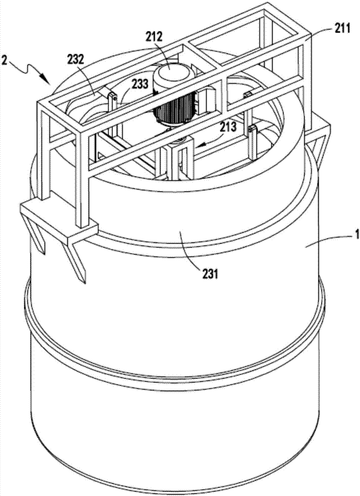
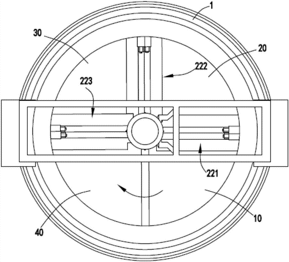
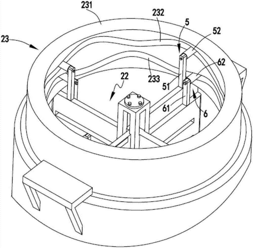
[0044] like Figure 1 to Figure 13 As shown, a rotary beating equipment includes a slurry tank 1, the slurry tank 1 is used to hold slurry; a rotary beating part 2, the rotary beating part 2 includes a power mechanism 21, a beating mechanism 22 and a guide Mechanism 23, the beating mechanism 22 divides the slurry tank 1 into the original slurry area 10, the primary slurry area 20, the secondary slurry area 30 and the qualified slurry area 40, and the beating mechanism 22 is driven by the power mechanism 21 Under the guiding action of the lower and guiding mechanism 23, it rotates along the central axis of the slurry tank 1 while making up and down alternating movements to beat the slurry in each area of the slurry tank 1 step by step.
[0045]By dividing the stock tank 1 into four areas, the original stock area 10, the primary stock area 20, the secondary stock area 30 and the qualified stock area 40, the textile stock is transferred from the original stock stock area 10 to ...
Embodiment 2
[0061] like Figure 1 to Figure 13 As shown, the components that are the same as or corresponding to those in the first embodiment are marked with the corresponding reference numerals in the first embodiment. For the sake of simplicity, only the differences from the first embodiment will be described below. The difference between the second embodiment and the first embodiment is: the first-level beating board a2211, the second-level beating board a2221, the third-level beating board a2231, the first-level beating board b2212, the second-level beating board b2222 and the third-level beating board The lower ends of the b2232 are all provided with supporting plates 8, and the upper surfaces of the supporting plates 8 are arranged in a wave shape.
Embodiment 3
[0063] like Figure 14 and Figure 15 As shown, the parts that are the same as or corresponding to those in the second embodiment are marked with the corresponding reference numerals in the second embodiment. For the sake of simplicity, only the differences from the second embodiment will be described below. The difference between the third embodiment and the second embodiment is that the feed troughs on the primary beating plate a2211, the secondary beating plate a2221 and the tertiary beating plate a2231 are set to be horizontal, and the cutters 3 in the feed trough It is also arranged horizontally along the feed trough, and the discharge troughs on the primary beating plate b2212, the secondary beating plate b2222 and the tertiary beating plate b2232 are set in an inclined shape, and the cutter b4 in the discharge trough is also set along the outlet. The trough is set in an inclined shape, so that when the cutter a3 and the cutter b4 intersect, the intersection of the two ...
PUM
 Abstract
Description
Claims
Application Information
 - R&D
- Intellectual Property
- Life Sciences
- Materials
- Tech Scout
- Unparalleled Data Quality
- Higher Quality Content
- 60% Fewer Hallucinations
Browse by: Latest US Patents, China's latest patents, Technical Efficacy Thesaurus, Application Domain, Technology Topic, Popular Technical Reports.
© 2025 PatSnap. All rights reserved.Legal|Privacy policy|Modern Slavery Act Transparency Statement|Sitemap|About US| Contact US: help@patsnap.com


