
A positive tension compensation device for warp knitting

A compensation device and tension technology, applied in the field of warp knitting positive tension compensation device, can solve the problems of tension compensation lag, insufficient performance, uneven yarn tension, etc., to achieve the effect of tension

Active Publication Date: 2019-01-29
JIANGNAN UNIV
View PDF7 Cites 0 Cited by
  • Summary
  • Abstract
  • Description
  • Claims
  • Application Information

AI Technical Summary

Problems solved by technology

However, these tension compensation methods have a phenomenon of compensation lag in a loop forming process, that is, negative tension compensation
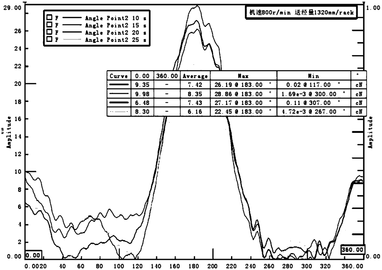
[0004] Negative tension compensation has a certain tension compensation ability to a certain extent, but it makes the warp tension fluctuate, resulting in uneven yarn tension, forming a large warp tension peak ( figure 1 is a typical peak), there is still the problem of tension compensation hysteresis, which cannot meet the requirements of some yarns with low strength and insufficient performance, such as spun yarns
[0005] At present, no positive tension compensation device has been found, and it is necessary to develop a warp knitted positive tension compensation device to overcome these defects in the negative tension compensation

Method used


Image

  • A positive tension compensation device for warp knitting
  • A positive tension compensation device for warp knitting
  • A positive tension compensation device for warp knitting

Examples


Embodiment 1

[0034] Such as figure 1 Shown is a typical tension fluctuation curve.

[0035] figure 1 It is on the KS4-EL warp knitting machine, only GB2 is used, 83.3dtec polyester low elastic yarn is fully worn, the lapping weave is 1-0 / 1-2 / / , and the let-off is 1320mm / rack. The tension fluctuation obtained from the test curve.

[0036] From figure 1 It can be seen that the main peak appears in the range of 100°-250° of the main axis, and the maximum, minimum and average value of the tension value can be read.

[0037] The relationship between △θ and △H is: △θ=△H / R, where R is the length of the steel plate;

[0038] The relationship between △a and △i is: △a=k·△i, where k is a constant term.

Embodiment 2

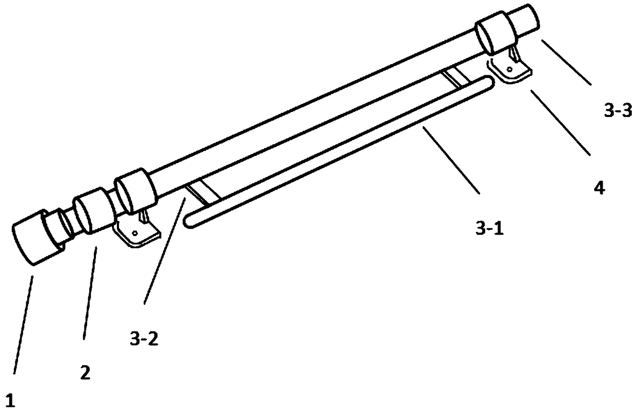
[0040] Such as figure 2 As shown, it is a schematic diagram of functional components of warp knitting positive tension compensation device, including: motor drive device 1, coupling 2, rigid tension rod 3-1, steel plate 3-2, shaft 3-3, bearing seat 4; Described bearing seat 4 can be installed on the frame of warp knitting machine, and described bearing seat 4 is sleeved with shaft 3-3, and one end of described shaft 3-3 is provided with coupling 2, and described shaft coupling 2 The other end is provided with a motor drive device 1, and the coupling 2 is connected to the shaft of the motor drive device 1; the rigid tension rod 3-1 is connected to the shaft 3-3 through a steel plate 3-2.

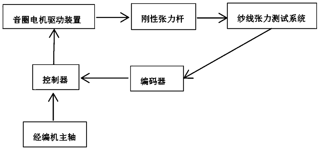
[0041] Such as image 3Shown is the warp-knitted positive compensation device and its working flow chart of the present invention. The warp knitting positive tension compensation device includes a motor drive device 1 and a rigid tension rod 3-1; the motor drive device 1 drives and control...


PUM


Abstract

The invention discloses a positive tension compensating device for tricot knitting and belongs to the field of tricot knitting tension adjustment. According to the device, bearing supports are arranged on a machine rack, a shaft is arranged on the bearing supports in a sleeved mode, a steel plate is arranged on the shaft, a rigid tension rod is connected with the shaft through the steel plate, a coupler is arranged at one end of the shaft, and a voice coil motor is connected with shaft through the coupler; the voice coil motor is connected with a controller; the controller is connected with a main shaft of a tricot machine, and a yarn tension test system is connected with an encoder which is connected with the controller. According to the positive tension compensating device, firstly, the warp tension fluctuation is measured through a resistance strain type yarn tension meter, then based on the primary crest position and the crest peak amplitude in a yarn tension measuring result, the rotation of the voice coil motor is adjusted through the controller so as to change the size of the bobbing angular displacement theta of the rigid tension rod, the crest is reduced, so that the size of the yarn tension is changed uniformly, accordingly, the warp yarn compensation amount is changed, and the positive compensation of the warp yarn tension is achieved.

Description

technical field [0001] The invention relates to a warp knitting positive tension compensation device, which belongs to the field of warp knitting tension adjustment. Background technique [0002] In the process of warp knitting, due to the difference between the amount of yarn consumption and the amount of yarn feeding during knitting, the tension of the warp yarn will fluctuate. Excessive tension fluctuations will easily cause yarn breakage and uneven coils, affecting product quality and production efficiency. . [0003] The current tension compensation device generally consists of a tension element and a tension rod. One end of the tension element is fixed on the frame through a connecting piece, and the other end is fixed to the tension rod. The warp tension is compensated by the elasticity and elastic recovery performance of the tension element. It is also reported that by changing the length of the tension piece, and then changing the working torque of the compensation...

Claims


Application Information

Patent Timeline
Patent Type & Authority Patents(China)
IPC IPC(8): D04B27/12D04B27/14
CPCD04B27/12D04B27/14
Inventor 缪旭红万爱兰孙帅陈晴马丕波
Owner JIANGNAN UNIV
Learn More