Orthogonal laminated wood shear wall with replaceable wall feet

A shear wall and glulam technology, applied in the direction of walls, building components, earthquake resistance, etc., can solve the problems of difficult repair and high repair costs, and achieve the effects of reducing repair costs, high cost performance, and simple production.

Inactive Publication Date: 2017-09-22
TONGJI UNIV
View PDF8 Cites 11 Cited by
  • Summary
  • Abstract
  • Description
  • Claims
  • Application Information

AI Technical Summary

Problems solved by technology

[0006] The object of the present invention is to provide a kind of cross-glued wood shear wall with replaceable foot energy-dissipating components that can reduce earthquake disasters of engineering structures, so as to reduce earthquake disasters of engineering structures and solve the problem of existing cross-glued wood shear walls. The problem that the structure is not easy to repair or the repair cost is high after a major earthquake

Method used


Image

  • Orthogonal laminated wood shear wall with replaceable wall feet
  • Orthogonal laminated wood shear wall with replaceable wall feet
  • Orthogonal laminated wood shear wall with replaceable wall feet

Examples


Embodiment 1

[0030] Embodiment 1: as figure 1 As shown, the cross-glued wood shear wall with replaceable energy-dissipating components of the present invention includes a cross-glued wood shear wall 11, a replaceable foot member and its connector, and a middle connector 31 of the shear wall; For the cross-glued timber shear wall 11, a part of the foot of the wall is excavated for each piece of wall to install replaceable foot components and their connectors.

Embodiment 2

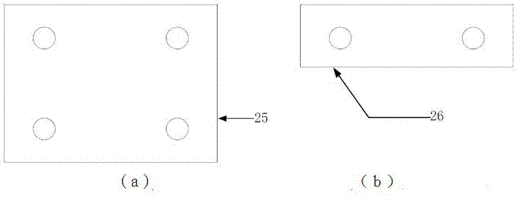
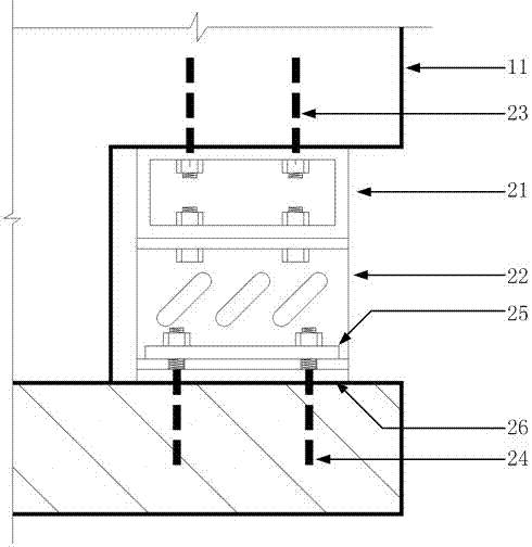
[0031] Embodiment 2: as Figure 2 to Figure 6As shown, the first planting bar 23 and the second planting bar 24 are made of high-strength screw or high-grade rebar to ensure sufficient tensile and shear strength. The first planting bar 23 is pre-embedded in the orthogonal In the glulam shear wall, the extension length of the end is enough to install the box-shaped pad 21; Backing plate 26 and I-shaped energy dissipation member 22 . The box-shaped mattress 21 is made of ordinary carbon structural steel by welding, and the soft steel I-shaped energy-dissipating member 22 is made of low-yield point steel by welding. The first steel backing plate 25 and the second steel backing plate 26 are made of ordinary carbon structural steel, and the bolts are high-strength bolts. First install the box-shaped pad 21, and tighten the nuts of the first planting bar 23, then put the second steel backing plate 26 into the installation position, then put the I-shaped energy-dissipating member 2...

Embodiment 3

[0032] Embodiment 3: as Figure 7 As shown, the ribbed angle steel 31 can be made of ordinary angle steel, and the stiffeners are welded on the angle steel by welding; the side where the ribbed angle steel 31 is connected with the cross-glued wood shear wall 11 has a plurality of standard round holes, through Use nails or self-tapping screws to securely connect the ribbed angle steel 31 to the cross-laminated wood shear wall 11; the other side of the ribbed angle steel 31 has multiple oblong holes, through which the high-strength bolts are used to connect with the floor, and apply The pretightening force, the number of high-strength bolts and the pretightening force must be designed so that the horizontal friction force provided has an appropriate value. When the structure is subjected to little horizontal action, the friction force provided by the pretightening force is sufficient to resist the horizontal force. The bolts There is no sliding between the bolt and the ribbed an...


PUM


Abstract

The invention relates to an orthogonal laminated wood shear wall with replaceable wall feet. The orthogonal laminated wood shear wall is composed of an orthogonal laminated wood shear wall body, box-type cushion tools, I-shaped flexible steel energy-dissipation members, steel cushion plates, embedded rebars and ribbed angle steel. Notches where members can be replaced are symmetrically reserved in the two feet of the orthogonal laminated wood shear wall body. The box-type cushion tools are firmly connected through the embedded rebars in the orthogonal laminated wood shear wall body. Upper flanges of the I-shaped flexible steel energy-dissipation members are firmly connected with the box-type cushion tools through bolts. Lower flanges of the I-shaped flexible steel energy-dissipation members are firmly connected through the embedded rebars in a foundation or a floor. In the middle of the bottom of the orthogonal laminated wood shear wall body, standard circular holes are formed in the face, making contact with the shear wall body, of the ribbed angle steel, and the angle steel is firmly connected with the orthogonal laminated wood shear wall body by nails or self-tapping screws via the circular holes. Long circular holes are formed in the other face of the angle steel, and the angle steel is connected with the floor or the foundation through high-strength bolts. The high-strength bolts apply pretension force, so that during a small earthquake, the shear resistance at the junction between the angle steel and the floor or between the angle steel and the foundation is sufficient, and during a medium earthquake or a severe earthquake, the high-strength bolts and the angle steel can slide relatively.

Description

technical field [0001] The invention relates to the field of construction engineering, in particular to an orthogonal glued wood shear wall with replaceable energy-consuming components for reducing earthquake disasters of engineering structures. Background technique [0002] Earthquakes are sudden, unpredictable, and occur frequently, causing huge losses to human society. my country is one of the countries with frequent land earthquakes, especially the frequent large earthquakes in recent years, which have caused serious earthquake damage to building structures. [0003] Cross-laminated timber is a factory prefabricated engineered wood product in the form of rectangular, straight and flat panels formed by at least three layers of solid wood sawn timber or structural composite panels orthogonally formed by pressing with structural adhesives. As far as the structural performance of CLT is concerned, CLT panels can be used as load-bearing panels and shear walls compared to oth...

Claims


Application Information

Patent Timeline
Patent Type & Authority Applications(China)
IPC IPC(8): E04B2/00E04B1/98E04H9/02
CPCE04B2/00E04H9/021
Inventor 李征邹桃何敏娟
Owner TONGJI UNIV
Why Eureka
Try Eureka