A layered high-power wind generator with automatic speed control

A high-power, layered technology, applied in the direction of engines, wind turbines, machines/engines, etc., can solve the problems of three-blade wind turbines that cannot be used to generate electricity, the price is unacceptable to ordinary families, and the utilization rate of wind power is not high. Improve wind utilization, increase air pressure, and improve the effect of strong wind resistance

Active Publication Date: 2019-01-04
王渊芃
View PDF4 Cites 0 Cited by
  • Summary
  • Abstract
  • Description
  • Claims
  • Application Information

AI Technical Summary

Problems solved by technology

Of course there are bigger ones, but the price is unacceptable for ordinary families
Three-leaf wind turbines cannot generate electricity using breezes below level 3 or low-speed winds
In addition, the utilization rate of wind power is not high, and wind turbines will be damaged when encountering strong winds of level 7-10

Method used


Image

  • A layered high-power wind generator with automatic speed control

Examples


Embodiment 1

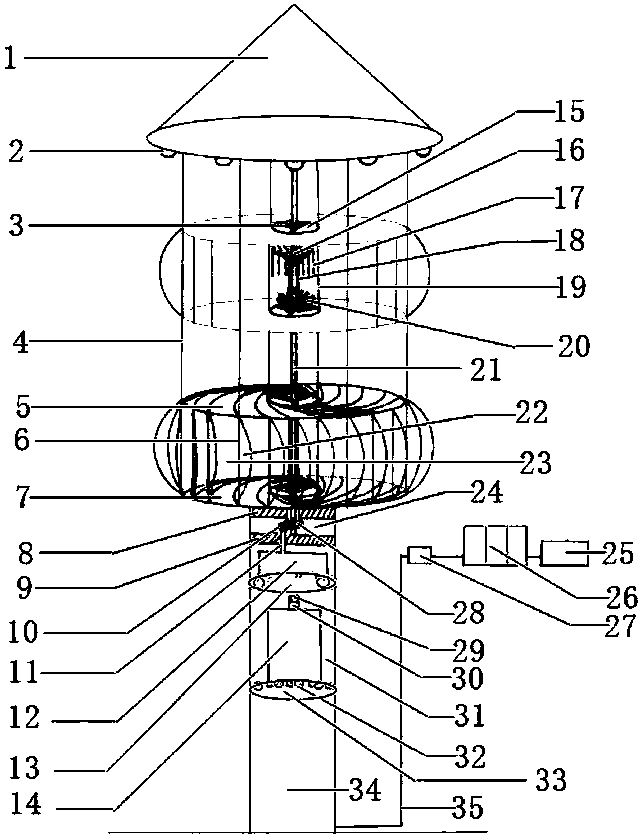
[0020] Such as figure 1 As shown, an automatic speed control layered high-power breeze generator is composed of four parts: a pole mechanism, a wind wheel mechanism, a power generation mechanism, and a charging mechanism. The pole mechanism consists of a central shaft 21, a top cover 1, an electrical appliance Interface 2, main support 9, secondary support 8, upper partition 13, transmission compartment 24, motor compartment 31, lower partition 33, air intake hole 32, electric pole 34, the electric pole 34 is a cavity structure, the main Support 9 and secondary support 8 are all arranged on the top of pole 34 and secondary support 8 is positioned at the top of main support 9, and the lower end of central axis 21 is fixed on the main support 9, and the upper end of central axis 21 passes secondary support 8 and extends to secondary Outside the bracket 8, the top cover 1 is arranged on the top of the central axis 21, and a plurality of electrical interfaces 2 are arranged at the...


PUM


Abstract

The invention belongs to the technical field of wind power generation devices and particularly relates to an automatic speed control layered high-power breeze generator. The invention aims at providing the automatic speed control layered high-power breeze generator which is not limited by the wind direction. The automatic speed control layered high-power breeze generator is composed of an electric pole mechanism, a wind wheel mechanism, a power generation mechanism and a charging mechanism. The electric pole mechanism is composed of a central shaft, a top cover, electric appliance interfaces, a primary bracket, a secondary bracket, an upper partition plate, a transmission cabin, a motor cabin, a lower partition plate, air inlet holes and an electric pole. The primary bracket and the secondary bracket are both arranged on the upper portion of the electric pole, and the secondary bracket is located above the primary bracket. The lower end of the central shaft is fixed to the primary bracket. The top cover is arranged at the top end of the central shaft. The multiple electric appliance interfaces are arranged at the edge of the lower end of the top cover. The upper partition plate and the lower partition plate are arranged in a cavity structure of the electric pole in sequence from top to bottom. The motor cabin is formed between the upper partition plate and the lower partition plate. The transmission cabin is formed between the primary bracket and the secondary bracket.

Description

technical field [0001] The invention belongs to the technical field of wind power generating devices, and in particular relates to an automatic speed-control layered high-power breeze generator. Background technique [0002] As a clean and renewable energy, wind energy has been paid more and more attention by countries all over the world. At present, the household wind turbines on the market generally have a relatively small power, ranging from a few hundred watts to about 1KV. Of course, there are bigger ones, but the price is unacceptable for ordinary families. The three-leaf wind turbine cannot generate electricity by using the breeze below level 3 or the low-speed wind. In addition, the utilization rate of wind power is not high, and wind turbines will be damaged when encountering 7-10 strong winds. Contents of the invention [0003] The purpose of the present invention is to provide an automatic speed control layered high-power breeze generator which is not limited...

Claims


Application Information

Patent Timeline
Patent Type & Authority Patents(China)
IPC IPC(8): F03D3/06F03D80/60F03D80/00F03D7/06
CPCY02E10/74
Inventor 王渊芃
Owner 王渊芃
Why Eureka
Try Eureka