

Microfluid pump
A fluid pump and micro-quantity technology, which is applied to parts, pumps, and pump components of pumping devices for elastic fluids, can solve the problems of low pump fluid efficiency, high noise, and complex structure, and achieve low noise and fluidity. The effect of high efficiency and simple structure
- Summary
- Abstract
- Description
- Claims
- Application Information
AI Technical Summary
Problems solved by technology
Method used
Image

Examples
Embodiment approach
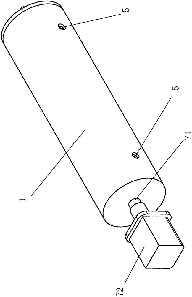
[0034] The screw rod 71 of the present invention is a single-rotation reciprocating screw rod. In the second embodiment of the present invention, a unidirectional motor is used to cooperate with a single-rotation reciprocating screw rod to form a driving mechanism, wherein the structure of the single-rotation reciprocating screw rod is not provided with a double helix on the rod body, and a connecting double screw is provided at the end of the rod body. The connecting part of the spiral, when the blade rotates from one of the spiral tracks to the end of the rod body, the blade passes through the connecting part and enters the other spiral track to move in reverse, so that the blade moves back and forth.
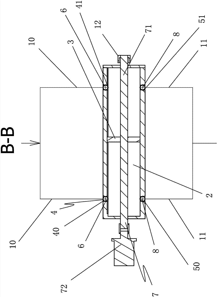
[0035] In the present invention, a guide cylinder 9 is provided in the pump body 1, and the blade 3 is an iron blade. The blade 3 is sleeved on the guide cylinder 9 and is dynamically sealed with the outer wall of the guide cylinder 9. The wire The rod 71 is arranged in the g...
PUM
 Abstract
Description
Claims
Application Information