
Superconducting phase change electric heater

A technology of electric heaters and superconducting phases, applied in the field of superconducting phase change electric heaters, can solve problems such as low electrothermal conversion efficiency, low comfort, and slow heating speed

Inactive Publication Date: 2017-09-22
北京世纪清科环保设备有限责任公司
View PDF11 Cites 2 Cited by
  • Summary
  • Abstract
  • Description
  • Claims
  • Application Information

AI Technical Summary

Problems solved by technology

The heating methods of the above types of electric heaters have their own defects in varying degrees, such as low electrothermal conversion efficiency, slow heating speed, slow start at low temperature, loud noise during work, poor safety, and low comfort, etc.

Method used


Image

  • Superconducting phase change electric heater
  • Superconducting phase change electric heater
  • Superconducting phase change electric heater

Examples


Embodiment 1

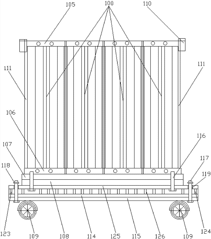
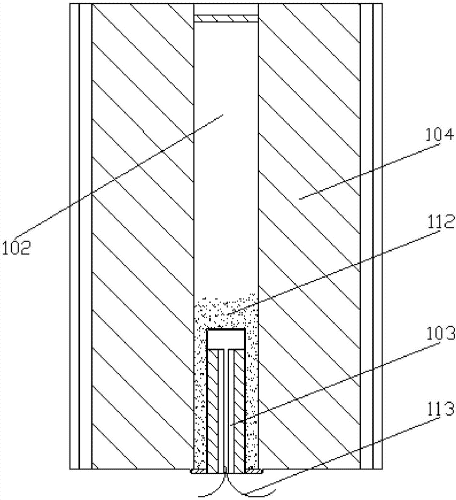
[0030] Such as Figure 1 to Figure 2 Shown: the superconducting phase-change electric heater of the embodiment of the present invention includes several phase-change superconducting heating devices 100, and only one phase-changing superconducting heating device 100 can be selected, and the phase-change superconducting heating device 100 includes A metal radiator 104, the metal radiator 104 is provided with a vacuum steel pipe 102, the vacuum steel pipe 102 is equipped with a phase change superconducting liquid, the bottom of the vacuum steel pipe 102 is provided with a groove 112, and the groove 112 is provided with There is a PTC heating rod 103, and the PTC heating rod 103 is closely attached to the wall of the groove 112, and the PTC heating rod 112 is connected with a wire 113; the top of the phase change superconducting heating device 100 is passed through the first connecting button 105, the bottom of the phase change superconducting heating device 100 is connected throu...

Embodiment 2

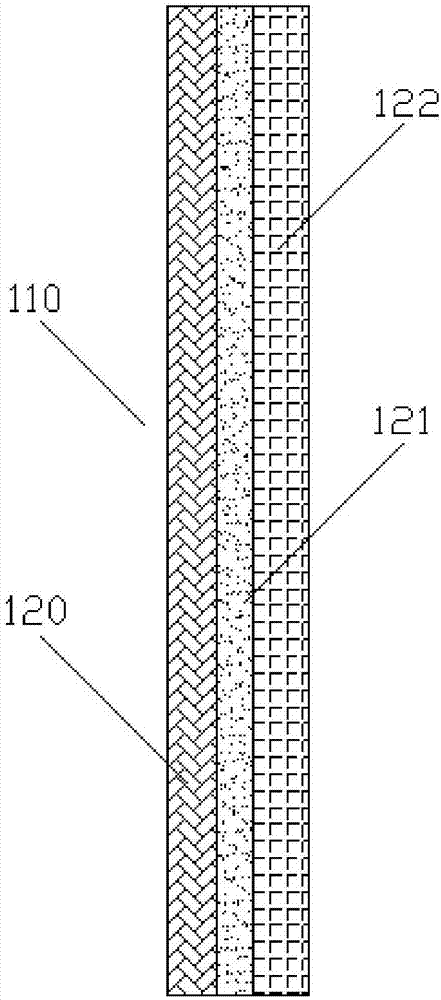
[0039] Such as image 3 As shown, in the superconducting phase change electric heater provided by the present invention, on the basis of the above structure, the outer sides of the phase change superconducting heating device 100 on both sides are provided with a flame retardant device 111, and the flame retardant The flame retardant device 111 includes a flame retardant skin 122 wherein:

[0040] The flame retardant surface layer 122 is leather made of low plasticizer polyvinyl chloride material, and a flame retardant is added inside the flame retardant surface layer 122, and an adhesive layer 121 is combined on one side of the flame retardant surface layer 122, and the low plasticizer polyvinyl chloride The flame retardant surface layer of vinyl material has the effect of anti-slip and wear resistance, and a flame retardant is added inside the flame retardant surface layer to make it have a flame retardant effect;

[0041] The adhesive layer 121 is an adhesive bonded to the ...


PUM


Abstract

The invention relates to a superconducting phase change electric heater. The superconducting phase change electric heater comprises a plurality of phase change superconducting electric heating devices. Each phase change superconducting electric heating device comprises a metal radiator internally provided with a vacuum steel pipe, wherein the vacuum steel pipe is internally filled with phase change superconducting liquid, a groove is formed in the bottom of the vacuum steel pipe and internally provided with a PTC heating bar, and the PTC heating bar is connected with a wire. The bottoms of the phase change superconducting electric heating devices are connected through second connecting buckles. A supporting frame is horizontally arranged at the bottoms of the second connecting buckles. A damping device is arranged below the supporting frame and fixedly arranged at the bottom of the supporting frame through an installing plate. A plurality of moving wheels are arranged at the bottom of the damping device. The provided superconducting phase change electric heater has the beneficial effects of being low in energy consumption, high in heat efficiency, rapid in heating, low in starting temperature, safe and comfortable, the width and the height can be changed according to the space size, and meanwhile good damping performance can be achieved.

Description

technical field [0001] The invention relates to a superconducting phase change electric heater. Background technique [0002] Heating in winter Heating is one of the important factors to improve the quality of life and office efficiency, mainly including various heating methods such as steam heat, water heat and electric heat. Electric heating has gradually occupied a larger heating market due to its advantages of safety and environmental protection, flexible adjustment and convenient use. There are many types of electric heaters currently on the market, including electric oil heaters, heat pipe electric heaters, convection electric heaters, halogen tube electric heaters, and far-infrared electric heaters. With the development of the national economy and the continuous improvement of people's quality of life, people's demand for electricity is increasing, and the contradiction of urban electricity supply is becoming more and more prominent, mainly in the shortage of electri...

Claims


Application Information

Patent Timeline
Patent Type & Authority Applications(China)
IPC IPC(8): F24D13/04F24D19/02
CPCF24D13/04F24D19/0203F24D2200/08
Inventor 陈云
Owner 北京世纪清科环保设备有限责任公司
Learn More