Eureka AIR delivers breakthrough ideas for toughest innovation challenges, trusted by R&D personnel around the world.

Omnidirectional wheel chassis capable of assisting in supporting and positioning

A technology of auxiliary support and omni-directional wheels, which is applied in the direction of the launch device, can solve the problems of low friction between the omni-directional wheels and the ground, complex connectors, side shifting, etc., and achieve the effect of easy implementation, simple structure, and elimination of influence

Inactive Publication Date: 2017-09-22
SOUTH CHINA UNIV OF TECH
View PDF6 Cites 1 Cited by
  • Summary
  • Abstract
  • Description
  • Claims
  • Application Information

AI Technical Summary

Problems solved by technology

[0002] At present, the general launching mechanism needs to have a degree of freedom of plane rotation. Generally, it is necessary to add a pan / tilt to the chassis to realize this function. This structure is compared with the structure of directly using the omnidirectional wheel chassis to realize a plane rotation degree of freedom. It needs to add an additional motor to drive, and requires more complicated connections
However, the degree of freedom of plane rotation is directly achieved by using the omnidirectional wheel chassis. Due to the low friction between the omnidirectional wheel and the ground, it is easy to shift sideways due to the recoil force of the launch when the fixed-point launch is realized. It is time-consuming and labor-intensive to adjust the position again when launching again.

Method used


Image

  • Omnidirectional wheel chassis capable of assisting in supporting and positioning
  • Omnidirectional wheel chassis capable of assisting in supporting and positioning
  • Omnidirectional wheel chassis capable of assisting in supporting and positioning

Examples


Embodiment Construction

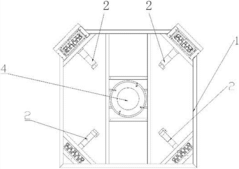
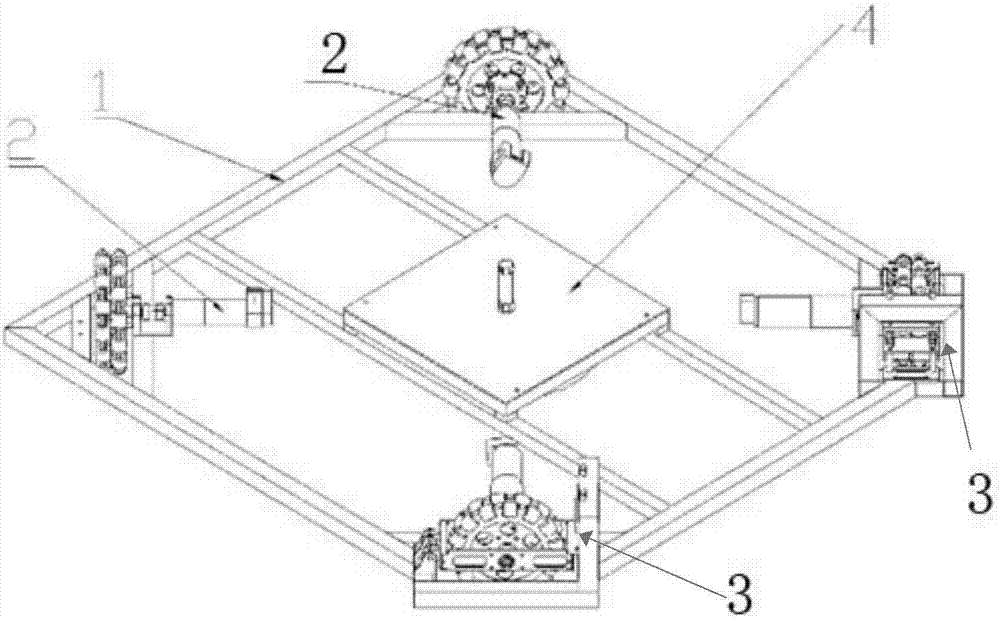
[0027] The technical solution adopted by the omni-directional wheel chassis that can assist support and positioning of the present invention will be further described below in conjunction with the accompanying drawings and embodiments.

[0028] like figure 1 and figure 2 As shown, an omnidirectional wheel chassis that can assist support positioning, including:

[0029] The chassis frame 1 is a square frame structure;

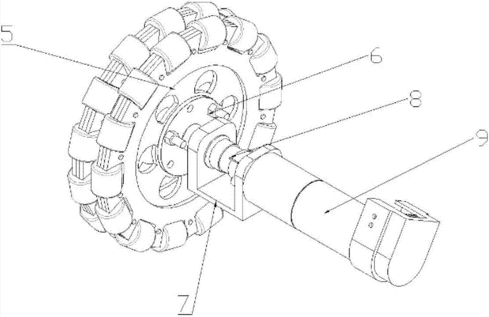
[0030] The four omnidirectional wheel drive systems 2 are respectively arranged at the corners of the chassis frame 1, and the chassis frame 1 is provided with through holes, and the four omnidirectional wheel drive systems 2 are fixed on the said chassis frame 1 by bolts in the through holes. The corresponding position of the chassis frame 1;

[0031] The launch fastening mechanism 4 is fixedly arranged at the center position of the chassis frame 1, and includes a cylinder 15, a cylinder fixing plate 14, a plane bearing 16, and a launch fixing block 17 from...


PUM


Abstract

The invention discloses an omnidirectional wheel chassis capable of assisting in supporting and positioning. The omnidirectional wheel chassis comprises a chassis frame, a plurality of omnidirectional wheel drive lines and a launching fastening mechanism, wherein the chassis frame is of a regular polygonal frame structure; the omnidirectional wheel drive lines are arranged at corners of the chassis frame correspondingly; and the launching fastening mechanism is fixed to the center position of the chassis frame and sequentially comprises an air cylinder, an air cylinder fixing plate, a plane bearing and a launching fixing block from top to bottom, the air cylinder is vertically fixed to the air cylinder fixing plate, a piston rod of the air cylinder downwards extends and is fixedly connected with the launching fixing block, and the plane bearing is arranged between the air cylinder fixing plate and the launching fixing block. The launching fixing block makes contact with the ground, the omnidirectional wheel chassis is fixed to the ground through the friction (or the suction force of a suction cup) of rubber which is fixedly connected to the bottom of the launching fixing block, at the time, the whole chassis can rotate around the center, the plane rotating function of a launching mechanism is achieved, a pan-tilt effect is achieved, and the effect caused by launching recoil force can also be eliminated.

Description

technical field [0001] The invention relates to an omnidirectional wheel chassis, in particular to an omnidirectional wheel chassis capable of assisting support and positioning. Background technique [0002] At present, the general launching mechanism needs to have a degree of freedom of plane rotation. Generally, it is necessary to add a pan / tilt to the chassis to realize this function. This structure is compared with the structure of directly using the omnidirectional wheel chassis to achieve a plane rotation degree of freedom. Need to add an additional motor to drive, and need more complicated connectors. However, the degree of freedom of plane rotation is directly achieved by using the omnidirectional wheel chassis. Due to the low friction between the omnidirectional wheels and the ground, it is easy to shift sideways due to the recoil force of the launch when the fixed-point launch is realized. The re-launch needs to adjust the position, which is time-consuming and labo...

Claims


Application Information

Patent Timeline
IPC IPC(8): F41F7/00
CPCF41F7/00
Inventor 张东林诗峰胡洋陈泽达杨思敏黄梓田
Owner SOUTH CHINA UNIV OF TECH
Why Eureka
Eureka Blog
Learn More