

Method for improving precision of external reference calibration of multi-ocular camera based on multiple identification plate images
A multi-camera, precision calibration technology, which is applied in image analysis, image data processing, instruments, etc., can solve the problems of large modeling errors and inaccurate mutual positional relationships between multiple cameras, and achieve the effect of reducing errors
- Summary
- Abstract
- Description
- Claims
- Application Information
AI Technical Summary
Problems solved by technology
Method used
Image

Examples
specific Embodiment approach 1
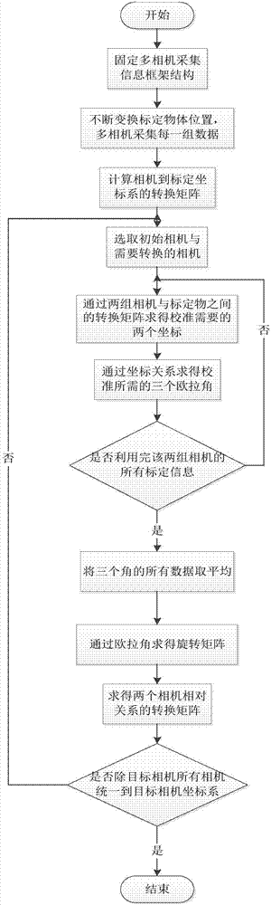
[0023] Specific implementation mode one: as figure 1 As shown, a method for improving the calibration accuracy of external parameters of a multi-eye camera based on multiple recognition calibration board images is implemented in the following steps:
[0024] Step 1: Set the black and white checkerboard or two-dimensional code as the calibration object, move the calibration object to different positions, and obtain the calibration information of the calibration object through simultaneous observation by N groups of cameras (the N groups of cameras are labeled A, B, C...) at each position , image and point cloud information, a set of calibration information is obtained for each position, a total of i set of calibration information is obtained, where N is greater than or equal to 2; the calibration information of the calibration object is the 2D image obtained by camera observation, and the camera coordinate system is obtained Transformation matrix to the coordinate system formed...
specific Embodiment approach 2
[0034] Specific embodiment two: the difference between this embodiment and specific embodiment one is: the specific process of obtaining the conversion matrix of the calibration coordinate system in the step two is:
[0035] Group 1 calibration information:
[0036]
[0037] where matrix Represents the transformation matrix of the coordinate system formed by the camera A coordinate system to the first group of calibration objects, represents the rotation matrix, represents the translation matrix;
[0038] Group i calibration information:
[0039]
[0040] in The matrix represents the conversion matrix from the coordinate system of camera A to the coordinate system formed by the i-th group of calibration objects.
[0041] Other steps and parameters are the same as those in Embodiment 1.
specific Embodiment approach 3
[0042] Specific embodiment 3: The difference between this embodiment and specific embodiment 1 or 2 is that in the step 3, the initial camera and the camera to be converted are selected, and the two sets of cameras required for calibration are obtained through the conversion matrix between the two groups of cameras and the calibration object. The specific process of coordinates is:
[0043] The transformation matrix from coordinate system 1 to coordinate system 2 is The coordinate system 1 is the coordinate system formed by the calibration object in the first group of calibration information, and the coordinate system 2 is the coordinate system formed by the calibration object in the second group of calibration information; Represents the transformation matrix from coordinate system 1 to coordinate system 2 observed by camera A, Represents the transformation matrix from coordinate system 1 to camera A coordinate system; Numerically yes inverse of.
[0044]In the coord...
PUM
 Abstract
Description
Claims
Application Information