Flow battery charging and discharging control method and system thereof, and flow battery

A charge-discharge control, flow battery technology, applied in the direction of fuel cells, regenerative fuel cells, circuits, etc. Charge and discharge capacity and energy efficiency, optimize SOC usage range, improve performance and life effect

Active Publication Date: 2020-05-29
DALIAN RONGKE POWER
View PDF5 Cites 0 Cited by
  • Summary
  • Abstract
  • Description
  • Claims
  • Application Information

AI Technical Summary

Problems solved by technology

[0003] The flow batteries in the prior art have the following problems when charging and discharging: 1. Regardless of the influence of the flow battery on the performance and capacity of the battery at the end of charge (high SOC) and discharge (low SOC), direct charging The charge and discharge are carried out in the way of discharging to the cut-off condition; while the electrochemical polarization and concentration polarization of the flow battery increase at the end of charge and discharge, and the side reactions increase, resulting in the oxidation / reduction of the active material of the flow battery, making the flow battery The irreversible attenuation of the battery capacity affects the long-term operating life and stability of the flow battery; 2. The charge and discharge control method of the flow battery is single, resulting in a limited charge and discharge capacity of the flow battery, which cannot maximize the advantages of the flow battery Such as energy efficiency and capacity performance, etc.

Method used


Image

  • Flow battery charging and discharging control method and system thereof, and flow battery
  • Flow battery charging and discharging control method and system thereof, and flow battery
  • Flow battery charging and discharging control method and system thereof, and flow battery

Examples


Embodiment Construction

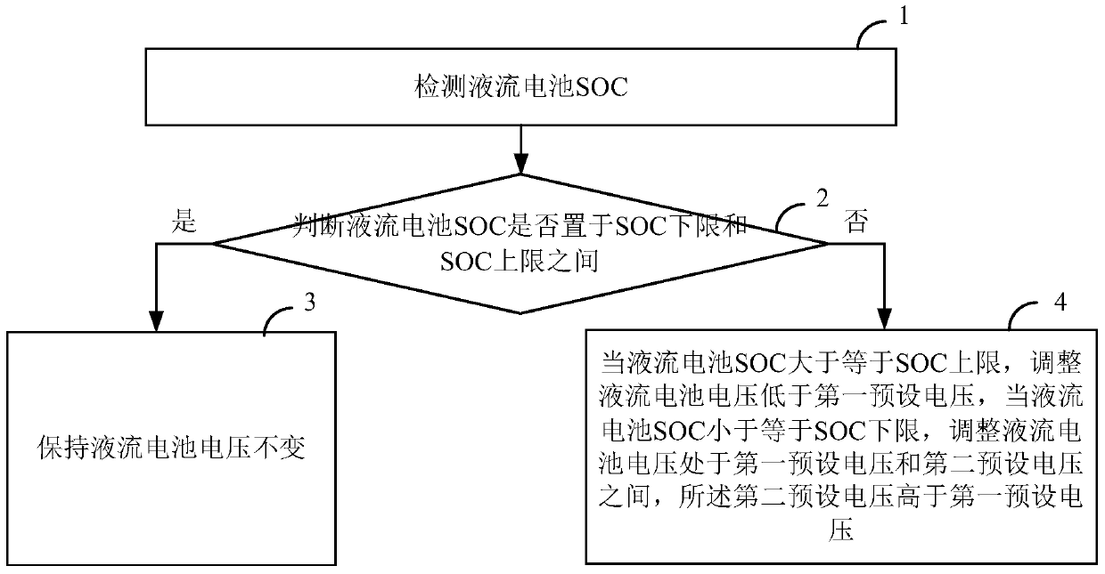
[0035] Such as figure 1 A method for controlling charge and discharge of a flow battery includes the following steps:

[0036] Step 1: Detect the SOC of the flow battery;

[0037] Step 2: Determine whether the SOC of the flow battery is between the lower limit of SOC and the upper limit of SOC, if yes, perform step 3, otherwise, perform step 4;

[0038] Step 3: Keep the voltage of the flow battery constant;

[0039] Step 4: When the SOC of the flow battery is greater than or equal to the SOC upper limit, adjust the voltage of the flow battery to be lower than the first preset voltage; when the SOC of the flow battery is less than or equal to the lower limit of SOC, adjust the voltage of the flow battery to be between the first preset voltage and the second Between preset voltages, the second preset voltage is higher than the first preset voltage;

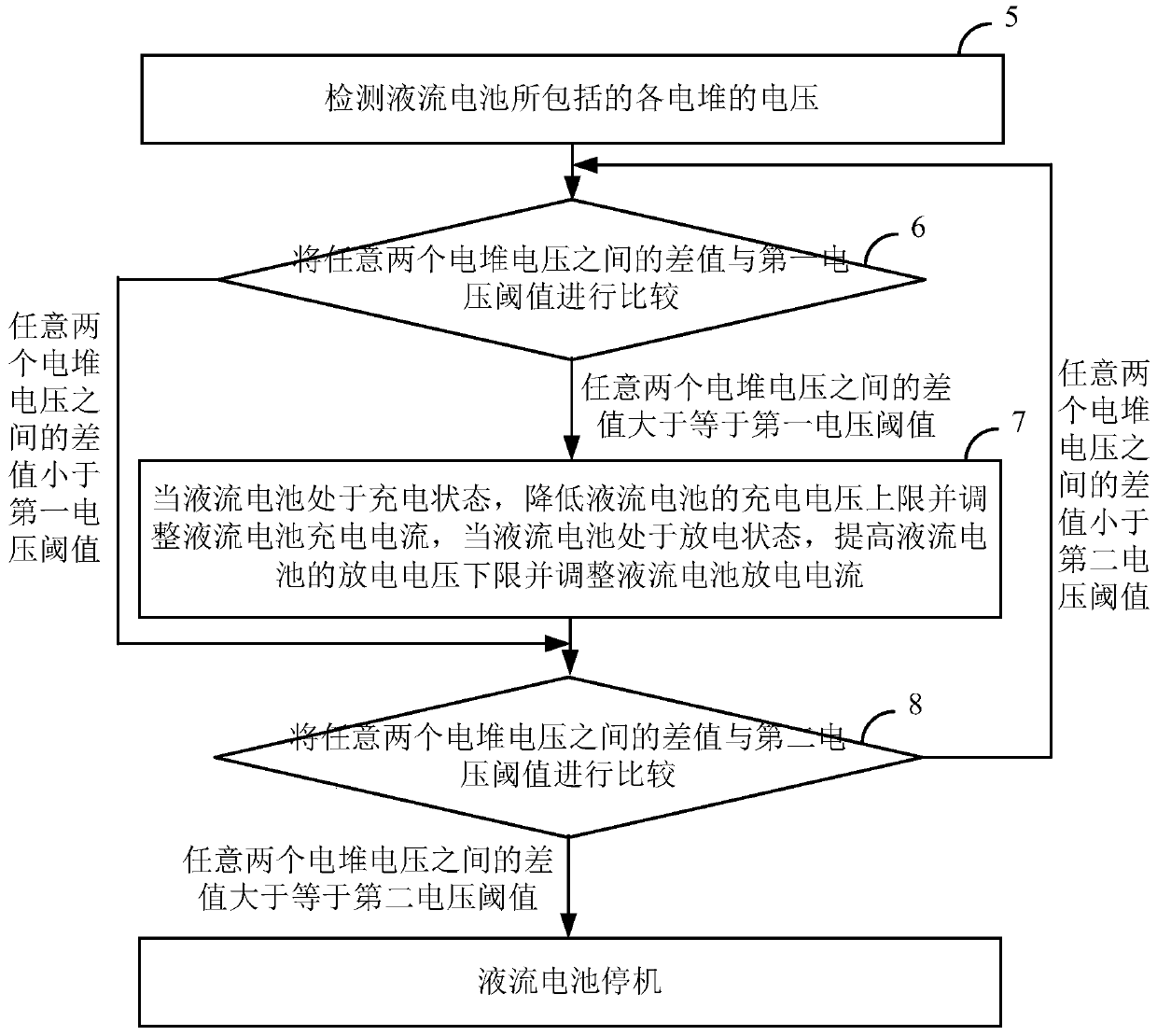
[0040] Such as figure 2 As shown, further, the method also includes the following steps after step 4:

[0041] Step 5: Detec...


PUM


Abstract

The invention discloses a charge-discharge control method and system of a redox flow battery and the redox flow battery. The method comprises the following steps of 1, detecting SOC of the redox flow battery; 2, judging whether the SOC of the redox flow battery is between an SOC lower limit and an SOC upper limit or not, if yes, executing the step 3, otherwise executing the step 4; 3, maintaining a voltage of the redox flow battery unchanged; and 4, adjusting the voltage of the redox flow battery to be lower than a first preset voltage when the SOC of the redox flow battery is larger than or equal to the SOC upper limit, and adjusting the voltage of the redox flow battery to be between the first preset voltage and a second preset voltage when the SOC of the redox flow battery is smaller than or equal to the SOC lower limit, wherein the second preset voltage is higher than the first preset voltage. By the method, the problems of side reaction is easy to generate in the redox flow battery under a high SOC condition and capacity attenuation of the redox flow battery caused by high SOC charge for a long time are prevented, and meanwhile, the upper limit of a charging voltage can be increased under a low SOC condition so as to improve charging quantity.

Description

technical field [0001] The invention belongs to the technical field of liquid flow batteries, and in particular relates to a charging and discharging control method and system for a liquid flow battery, and a liquid flow battery. Background technique [0002] Liquid flow battery has the advantages of flexible design (power and capacity can be independently designed), long service life, good charge and discharge performance, free site selection, high energy efficiency, safety and environmental protection, low maintenance cost, and easy realization of large-scale storage. Many advantages not available. In practical applications, liquid flow batteries can be widely used in renewable energy power generation systems such as wind energy and solar energy as energy storage systems, so that the generated electricity can be output continuously and stably; The power in low valleys is stored and output during peak power consumption to balance power supply and demand; in addition, it ca...

Claims


Application Information

Patent Timeline
Patent Type & Authority Patents(China)
IPC IPC(8): H01M8/18H01M8/04537H01M8/04858
CPCH01M8/04544H01M8/04865H01M8/188Y02E60/50
Inventor 马相坤张华民叱干婷赵海军权颖霍洋
Owner DALIAN RONGKE POWER
Why Eureka
Try Eureka