Electrolyte storage tank, redox flow battery, box-type redox flow battery system and charge-discharge control method of redox flow battery
A flow battery and electrolyte technology, which is applied in fuel cells, fuel cell additives, regenerative fuel cells, etc., can solve problems such as the inability to reflect the electrolyte inside the storage tank, the effective comprehensive consideration of SOC detection results, and achieve the utilization of electrolyte. The effect of increasing the rate, reducing the flow dead zone, and improving the monitoring accuracy
- Summary
- Abstract
- Description
- Claims
- Application Information
AI Technical Summary
Problems solved by technology
Method used
Image
Examples
Embodiment 1
[0081] 175kW / 200kWh kWh box-type liquid flow battery system, which includes a multi-stage leakage collection and alarm system, its structure is as follows Figure 5-Figure 6 As shown, the inside of the box-type flow battery system can be divided into three areas. The first part of the stack unit, various piping systems, heat exchange systems and battery management systems are placed at one end of the box, and the second part of the electrolyte storage tank It is placed in the middle section of the container body, and its two ends are installed with partitions to isolate it from the other two parts. The third part, the energy storage inverter system and the UPS, are placed side by side at the other end of the container body.
[0082] In the first part, the electric stack unit is placed at the bottom, the BMS cabinet is placed above the electric stack unit, the internal unit of the heat exchange system is placed above the electric stack, and the external unit is fixed on the top ...
Embodiment 2
[0091] The structure of the 60kW / 150kWh box-type flow battery system is as in Example 1. The material of the electrolyte storage tank is FRP, and the volume of the negative electrolyte storage tank is 1.3 times that of the positive electrolyte storage tank.
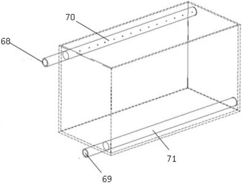
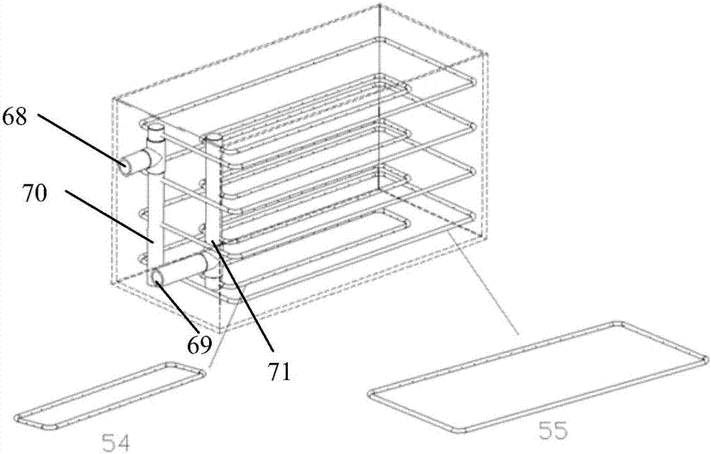
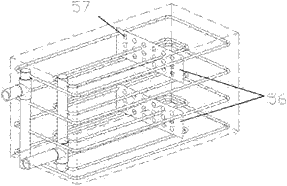
[0092] The inside of the electrolyte storage tank is provided with a multi-layer ring pipe, wherein the electrolyte return port 68, the electrolyte return line 70, and the ring pipe II 55 are connected in sequence; the ring pipe I 54, the electrolyte output line 71, and the electrolyte output port 69 are sequentially connected. The ring pipe II55 is placed in the center of the electrolyte storage tank, and the ring pipe I54 is placed near the tank wall of the electrolyte storage tank. The inner diameter of the section of the ring pipe II55 and the ring pipe I54 is 35mm, and several liquid holes are distributed on the ring pipe II55 and the ring pipe I54. Wait. The liquid holes on the ring pipe II55 are located on the out...
Embodiment 3
[0099] For a 100kW / 400kWh flow battery system, the electrolyte storage tank is made of resin material, the volume of the negative electrolyte storage tank is 1.25 times the volume of the positive electrolyte storage tank, and the liquid phase between the positive electrolyte storage tank and the negative electrolyte storage tank The part is provided with a pipeline 72 communicating with each other and a manual valve 74 located on the communication pipeline of the liquid phase part of the positive and negative electrolyte storage tanks. The internal structure of its storage tank is as in embodiment 1, and the multi-stage leakage liquid collection and alarm system is as in Figure 10 shown.
PUM
 Abstract
Description
Claims
Application Information
 - R&D
- Intellectual Property
- Life Sciences
- Materials
- Tech Scout
- Unparalleled Data Quality
- Higher Quality Content
- 60% Fewer Hallucinations
Browse by: Latest US Patents, China's latest patents, Technical Efficacy Thesaurus, Application Domain, Technology Topic, Popular Technical Reports.
© 2025 PatSnap. All rights reserved.Legal|Privacy policy|Modern Slavery Act Transparency Statement|Sitemap|About US| Contact US: help@patsnap.com


