Electrolyte storage tank, flow battery, box-type flow battery system, and charge and discharge control method for flow battery

A charge and discharge control, flow battery technology, applied in fuel cells, regenerative fuel cells, fuel cell additives, etc., can solve the problems of effective comprehensive consideration of SOC detection results, inability to reflect the electrolyte inside the storage tank, etc. The effect of improving utilization, reducing flow dead zone, and solving SOC lag

Active Publication Date: 2019-12-31
DALIAN RONGKE POWER
View PDF5 Cites 0 Cited by
  • Summary
  • Abstract
  • Description
  • Claims
  • Application Information

AI Technical Summary

Problems solved by technology

The SOC detection method of the liquid flow battery in the prior art only considers setting a detection point at the outlet of the stack, and does not effectively consider the SOC detection results within a certain period of time, and the detection results cannot reflect the actual SOC of the electrolyte inside the storage tank.

Method used


Image

  • Electrolyte storage tank, flow battery, box-type flow battery system, and charge and discharge control method for flow battery
  • Electrolyte storage tank, flow battery, box-type flow battery system, and charge and discharge control method for flow battery
  • Electrolyte storage tank, flow battery, box-type flow battery system, and charge and discharge control method for flow battery

Examples


Embodiment 1

[0081] 175kW / 200kWh kWh box-type liquid flow battery system, which includes a multi-stage leakage collection and alarm system, its structure is as follows Figure 5-Figure 6 As shown, the inside of the box-type flow battery system can be divided into three areas. The first part of the stack unit, various piping systems, heat exchange systems and battery management systems are placed at one end of the box, and the second part of the electrolyte storage tank It is placed in the middle section of the container body, and its two ends are installed with partitions to isolate it from the other two parts. The third part, the energy storage inverter system and the UPS, are placed side by side at the other end of the container body.

[0082] In the first part, the electric stack unit is placed at the bottom, the BMS cabinet is placed above the electric stack unit, the internal unit of the heat exchange system is placed above the electric stack, and the external unit is fixed on the top ...

Embodiment 2

[0091] The structure of the 60kW / 150kWh box-type flow battery system is as in Example 1. The material of the electrolyte storage tank is FRP, and the volume of the negative electrolyte storage tank is 1.3 times that of the positive electrolyte storage tank.

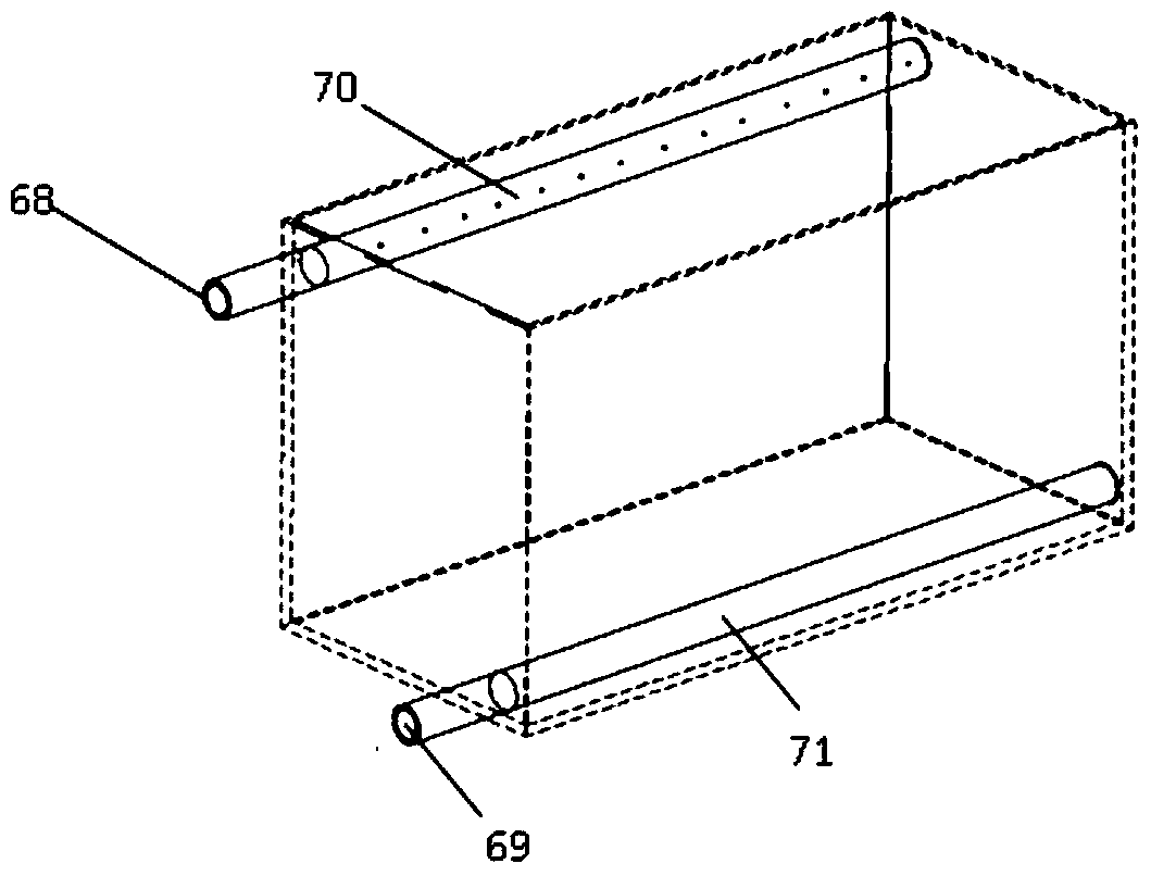
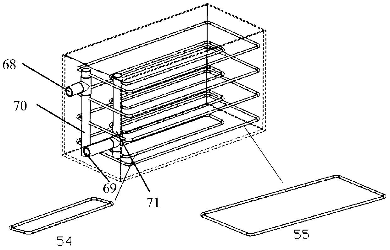
[0092] The inside of the electrolyte storage tank is provided with a multi-layer ring pipe, wherein the electrolyte return port 68, the electrolyte return line 70, and the ring pipe II 55 are connected in sequence; the ring pipe I 54, the electrolyte output line 71, and the electrolyte output port 69 are sequentially connected. The ring pipe II55 is placed in the center of the electrolyte storage tank, and the ring pipe I54 is placed near the tank wall of the electrolyte storage tank. The inner diameter of the section of the ring pipe II55 and the ring pipe I54 is 35mm, and several liquid holes are distributed on the ring pipe II55 and the ring pipe I54. Wait. The liquid holes on the ring pipe II55 are located on the out...

Embodiment 3

[0099] For a 100kW / 400kWh flow battery system, the electrolyte storage tank is made of resin material, the volume of the negative electrolyte storage tank is 1.25 times the volume of the positive electrolyte storage tank, and the liquid phase between the positive electrolyte storage tank and the negative electrolyte storage tank The part is provided with a pipeline 72 communicating with each other and a manual valve 74 located on the communication pipeline of the liquid phase part of the positive and negative electrolyte storage tanks. The internal structure of its storage tank is as in embodiment 1, and the multi-stage leakage liquid collection and alarm system is as in Figure 10 shown.


PUM


Abstract

The invention discloses an electrolyte storage tank, a redox flow battery, a box-type redox flow battery system and a charge-discharge control method of redox flow battery. A ring tube I and a ring tube II are arranged in the electrolyte storage tank, wherein the ring tube II communicates with an electrolyte return hole, the ring tube I communicates with an electrolyte output, the annular perimeter of the ring tube I is not equal to the annular perimeter of the ring tube II, and a plurality of liquid holes are formed in tube walls of both of the annular tube I and the annular tube II. By a multi-layer ring tube structure in the storage tank, an electrolyte flowing dead zone of an electrolyte in the storage tank is greatly reduced, the flowing of the electrolyte is more uniform, and the utilization of the electrolyte is effectively improved; and moreover, since the longitudinal distance between the electrolyte output and the electrolyte return hole is reduced, the problem of SOC lag is effectively solved, and the SOC monitoring accuracy of the redox flow battery is improved.

Description

technical field [0001] The present invention relates to the technical field of flow batteries, and in particular to an electrolyte storage tank, a flow battery, a box-type flow battery, and a charge and discharge control method for a flow battery. Background technique [0002] Large-scale, long-life, low-cost, and environmentally friendly energy storage technology is the main direction of energy storage technology development. Flow battery energy storage technology has become the first choice for large-scale energy storage technology because of its long service life, large energy storage scale, safety, reliability and pollution-free, good battery uniformity, fast response speed, and real-time direct monitoring of its charge and discharge status. One of the techniques. The configuration of corresponding energy storage can solve the unstable characteristics of renewable energy power generation to a large extent, realize smooth output and effectively adjust the time difference...

Claims


Application Information

Patent Timeline
Patent Type & Authority Patents(China)
IPC IPC(8): H01M8/18H01M8/04186H01M8/04537H01M8/04858
CPCH01M8/04208H01M8/04559H01M8/0488H01M8/188Y02E60/50
Inventor 吴静波张华民马相坤王宏博权颖王友韩希李俊
Owner DALIAN RONGKE POWER
Why Eureka
Try Eureka