
Ultra-high-voltage AC power grid high-voltage reactor optimization configuration method

A UHV AC and optimized configuration technology, applied to AC network circuits, circuit devices, electrical components, etc., can solve problems such as poor practicability, ineffective guidance of power system safe and stable operation system scheduling control requirements, etc., to improve practicability and reliability effect

Inactive Publication Date: 2017-09-22
STATE GRID CORP OF CHINA +3
View PDF1 Cites 5 Cited by
  • Summary
  • Abstract
  • Description
  • Claims
  • Application Information

AI Technical Summary

Problems solved by technology

At present, the high-resistance configuration of UHV transmission lines only considers the operating characteristics of UHV transmission lines. Generally, the compensation capacity is only set to meet the compensation for the capacitive charging power of UHV transmission lines, and does not consider the overall perspective of the power grid. The transmission line compensation required by the power frequency overvoltage of UHV transmission lines is related to the strength of the system at both ends of the line. Some studies focus on the theoretical analysis stage, and do not give some quantitative indicators to determine whether the reactive power compensation is reasonable. The application has great However, it does not effectively guide the safe and stable operation of the power system and the dispatching control requirements of the system, and the practicability is poor.

Method used


Image

  • Ultra-high-voltage AC power grid high-voltage reactor optimization configuration method
  • Ultra-high-voltage AC power grid high-voltage reactor optimization configuration method
  • Ultra-high-voltage AC power grid high-voltage reactor optimization configuration method

Examples


Embodiment Construction

[0068] The technical scheme of the present invention will be described in further detail below in conjunction with the accompanying drawings and calculation examples.

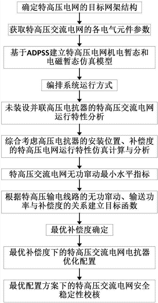
[0069] Such as figure 1 , figure 2 , image 3 , Figure 4 , Figure 5 , Image 6 As shown, a method for optimal configuration of high-voltage reactors in UHV AC power grids includes the following steps:

[0070] Step 1) Determine the target grid structure of the UHV power grid;

[0071] Step 2) Obtain the parameters of each electrical component of the UHV AC grid;

[0072] Step 3) Establishing the electromechanical transient and electromagnetic transient simulation models of the UHV power grid based on ADPSS;

[0073] (1) According to the 2020 planning and mode data of a certain domestic power grid, the electromechanical transient model of UHV power grid is established

[0074] (2) According to the specific data of the transformer, high reactance and line, the electromagnetic transient model that needs...


PUM


Abstract

The invention discloses an ultra-high-voltage AC power grid high-voltage reactor optimization configuration method, which comprises the steps: 1) determining a target framework structure of an ultra-high-voltage grid; 2) obtaining parameters of each electronic component in the ultra-high-voltage AC power grid; 3) establishing ultra-high-voltage power grid electromechanical transient and electromagnetic transient simulation models based on an ADPSS; 4) arranging system operation modes; 5) carrying out operating characteristic analysis on the ultra-high-voltage AC power grid having no parallel high-voltage reactors; 6) carrying out operation characteristic simulation calculation and analysis on the ultra-high-voltage power grid with installation position and compensation degree of the high-voltage reactor being taken into overall consideration; 7) calculating minimum level index of reactive play of the ultra-high-voltage AC power grid; 8) establishing an objective function according to relation of the reactive play of the ultra-high-voltage AC power grid, transmitting power and the compensation degree; 9) determining optimal compensation degree; 10) carrying out optimization configuration on the reactor of the ultra-high-voltage AC power grid; and 11) checking safety and stability of the ultra-high-voltage AC power grid. The method can be used for ultra-high-voltage AC power grid high-voltage reactor optimization configuration.

Description

technical field [0001] The invention relates to an optimal configuration method of a high-voltage reactor in an UHV AC power grid, in particular to a method for optimizing the configuration of a high-voltage reactor in an UHV AC power grid based on an optimal compensation degree, and belongs to the field of power grid planning, operation and control. Background technique [0002] Based on the national conditions of the reverse distribution of energy resources and load demand, the State Grid Corporation of China put forward the strategic goal of "developing UHV AC transmission and building a strong national grid". The development of coal power, large hydropower, large nuclear power, and large renewable energy bases is of great significance to realize the optimal allocation of resources across the country. The voltage level of UHV AC transmission lines is high, and the capacitive charging power generated by the line capacitance per unit length increases significantly. When the...

Claims


Application Information

Patent Timeline
IPC IPC(8): H02J3/18
CPCH02J3/1871H02J2203/20Y02E40/30
Inventor 李家珏王刚叶鹏马坤王信李胜辉杜凌艳孙峰朱钰邵宝珠戴鹏张涛程绪可
Owner STATE GRID CORP OF CHINA
Learn More