
A Switching Control Method of Dual Auxiliary Power Supply

A technology of auxiliary power supply and control method, applied in the direction of emergency power supply arrangements, electrical components, circuit devices, etc., can solve the problems of untimely response, cumbersome operation, high cost, etc., and meet the requirements of solving energy loss, reducing energy loss, and low power consumption Effect

Active Publication Date: 2020-01-07
DONGGUAN JUXING POWER
View PDF6 Cites 0 Cited by
  • Summary
  • Abstract
  • Description
  • Claims
  • Application Information

AI Technical Summary

Problems solved by technology

At present, most of the energy storage systems are in the following two ways: first, the mechanical switch is used. When the energy storage system is not needed, the mechanical switch is turned off, and the energy storage system does not work at all. This method is costly, especially for large currents. Occasionally, the price of the mechanical switch is quite expensive, and the response is not timely, and the operation is cumbersome; the second is the direct standby mode, which has a large standby power consumption due to the sampling of a single auxiliary power supply, resulting in a huge energy loss and increasing The number of charge and discharge cycles of the energy storage battery affects the battery life

Method used


Image

  • A Switching Control Method of Dual Auxiliary Power Supply
  • A Switching Control Method of Dual Auxiliary Power Supply
  • A Switching Control Method of Dual Auxiliary Power Supply

Examples


Embodiment 1

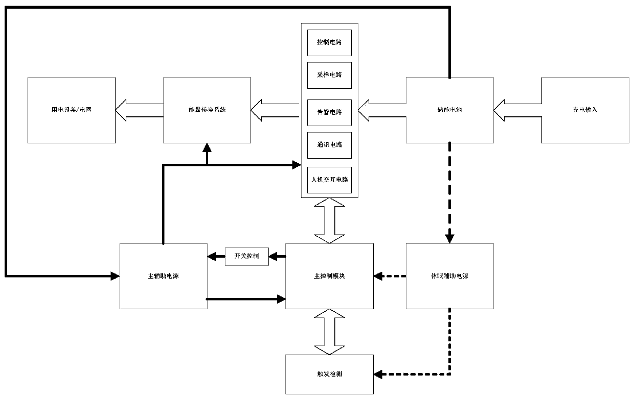
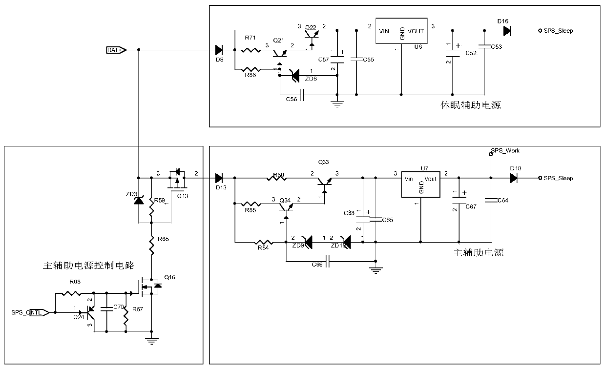
[0044] Embodiment 1: as Figure 1~2 , a switching control method of a dual auxiliary power supply, wherein the dual auxiliary power supply refers to a main auxiliary power supply and a dormant auxiliary power supply; the main control module is used as a switching control module;

[0045] Both the main auxiliary power supply and the dormant auxiliary power supply are powered by energy storage batteries;

[0046] The main auxiliary power supply and the dormant auxiliary power supply are respectively connected to the two power supply terminals of the main control module;

[0047] The main control module controls the main and auxiliary power supply through the switch control unit;

[0048] The main control module is also connected with a trigger detection circuit; the trigger detection circuit is powered by a dormant auxiliary power supply;

[0049] The main auxiliary power supply outputs control signals to the energy conversion module;

[0050]The dormant auxiliary power suppl...


PUM


Abstract

The invention discloses a switching control method for dual auxiliary power supplies. The dual auxiliary power supplies comprise a master control module, a main auxiliary power supply and a dormant auxiliary power supply, wherein the master control module controls the main auxiliary power supply by a switch control unit and is also connected with a trigger detection circuit, power is supplied to the trigger detection circuit by the dormant auxiliary power supply, and the main auxiliary power supply outputs a control signal to an energy conversion module. The dormant auxiliary power supply is in a working state all the way, (1) the main auxiliary power supply is in a shunting state under the control of the switch control unit when a trigger signal is not detected by the trigger detection circuit or the trigger signal is failure; and (2) the main auxiliary power supply is in a working state under the control of the switch control unit after the trigger signal is detected by the trigger detection circuit or a start-up instruction is received by the master control module. By the switching control method for the dual auxiliary power supplies, standby energy consumption can be saved, and rapid response is achieved.

Description

technical field [0001] The invention relates to a switching control method of dual auxiliary power supplies. Background technique [0002] At present, most energy storage systems will only intervene and play a role when the power is interrupted or people need to use them. Under normal circumstances, the energy storage system is in a non-working state. In the non-working state, the energy storage system is required to consume no power or consume as little power as possible. At present, most of the energy storage systems are in the following two ways: first, the mechanical switch is used. When the energy storage system is not needed, the mechanical switch is turned off, and the energy storage system does not work at all. This method is costly, especially for large currents. Occasionally, the price of the mechanical switch is quite expensive, and the response is not timely, and the operation is cumbersome; the second is the direct standby mode, which has a large standby power ...

Claims


Application Information

Patent Timeline
Patent Type & Authority Patents(China)
IPC IPC(8): H02J9/06
CPCH02J9/06Y02B70/30Y04S20/20
Inventor 廖跃飞纪业新
Owner DONGGUAN JUXING POWER
Learn More