
Distributed power supply cluster control node optimization deployment method and device

A distributed power and cluster control technology, applied in circuit devices, energy reserves, electrical components, etc., can solve problems such as power flow, complex fault mechanism and characteristics, and achieve the effects of ensuring safety, optimizing deployment locations, and optimizing operations.

Active Publication Date: 2017-09-22
GLOBAL ENERGY INTERCONNECTION RES INST CO LTD +3
View PDF5 Cites 0 Cited by
  • Summary
  • Abstract
  • Description
  • Claims
  • Application Information

AI Technical Summary

Problems solved by technology

[0003] However, due to its own intermittent, fluctuating, and random characteristics, the access of a single distributed power source to the power grid has a certain impact on the power grid, making the power flow and fault mechanism characteristics of the power grid more complicated, and affecting the distributed power generation. Control must be supported by an efficient information and communication platform

Method used


Image

  • Distributed power supply cluster control node optimization deployment method and device
  • Distributed power supply cluster control node optimization deployment method and device
  • Distributed power supply cluster control node optimization deployment method and device

Examples


Embodiment 1

[0089] Embodiment 1: The technical solution of the present invention is applicable to an isolated micro-grid environment. The distributed power supply nodes in the embodiments of the present invention may be devices with fixed installation positions such as wind turbines, photovoltaics, and energy storage, the monitoring nodes may be power quality monitoring devices, and the control nodes may be microgrid coordination controllers. Both the monitoring node and the control node are virtual nodes, and the physical location is the same as that of the distributed power supply node. Specifically:

[0090] Step 1, initialize the network, identify the distributed power nodes, power monitoring nodes, and control nodes in the isolated micro-grid, and all nodes have communication capabilities;

[0091] Step 2. Select the power quality monitoring device and the micro-grid coordination controller as detection nodes in the network, obtain the network connection status and network delay fro...

Embodiment 2

[0093] Embodiment 2: The technical solution of the present invention is applicable to the dynamic networking environment of electric vehicles. The distributed power supply node in the embodiment of the present invention is a charging pile / charging station with a fixed installation location, and the control node is a grid-connected coordination device. The number of electric vehicles connected to the charging pile / charging station is dynamically changing. The charging pile / charging station is connected to the grid for charging and discharging. Specifically:

[0094] Step 1, initialize the network, identify charging pile / charging station nodes and control nodes in the electric vehicle network, and all nodes have communication capabilities;

[0095] Step 2, select the grid-connected coordination device as the detection node in the network, and obtain the network connection status and network delay from the detection node to the power node, so as to determine the network coordina...


PUM


Abstract

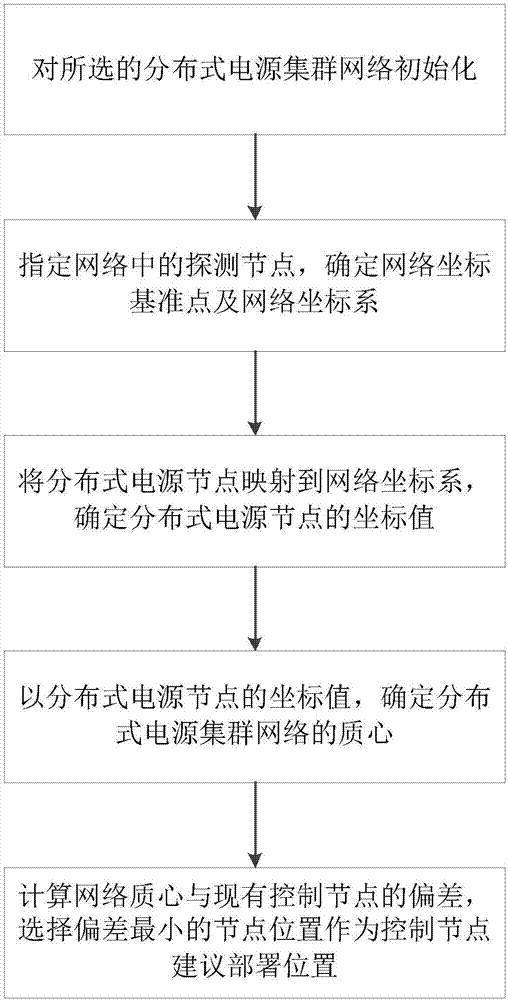
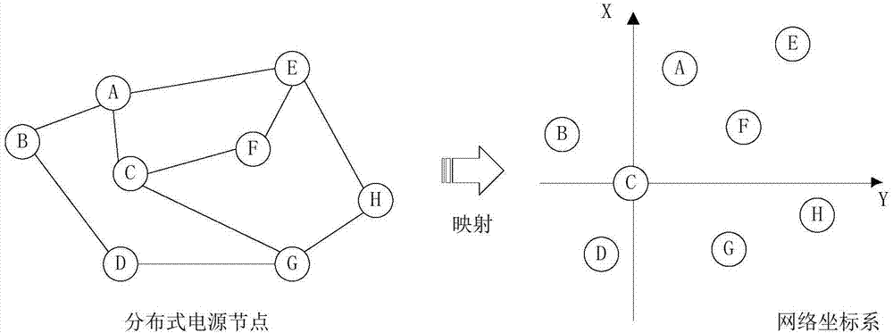
The invention provides a distributed power supply cluster control node optimization deployment method, which comprises the following steps: setting detection nodes in a distributed power supply cluster network and determining a network coordinate system; calculating coordinate values of the distributed power supply nodes according to network coordinates of the detection nodes; according to the coordinate values of the distributed power supply nodes, determining the center of mass of the distributed power supply cluster network; and determining deployment position of a control node according to the center of mass of the network. According to the technical scheme, network distance between the nodes of a distributed power supply is analyzed quantitatively based on the network coordinates, thereby eliminating the influence of inconformity of geographic distance and network distance, optimizing the deployment position of a controller and ensuring safe, stable and optimized operation of a power grid; and the network coordinates are obtained based on detection data, and the method and device can be suitable for flexible grid connection of the distributed power supply and have practical operability.

Description

technical field [0001] The invention belongs to the technical field of distributed power sources in power systems, and in particular relates to a method and device for optimal deployment of distributed power source cluster control nodes. Background technique [0002] With the increasing attention of the whole society such as the greenhouse effect and environmental pollution, green, environmentally friendly, efficient and flexible distributed power sources have gradually been popularized and applied. Distributed power mainly includes various types of renewable energy power generation systems (such as wind energy, solar energy, biomass energy, etc.), as well as various energy storage systems (chemical batteries, flywheels, molten salt heat storage, etc.), which is conducive to energy conservation and emission reduction, And it can adapt to the decentralized power demand and resource distribution, and the mutual backup with the large power grid can also improve the reliability ...

Claims


Application Information

Patent Timeline
Patent Type & Authority Applications(China)
IPC IPC(8): H04L12/24H04L12/26H02J3/38
CPCH02J3/381H04L41/12H04L43/0811H04L43/0852H02J2203/20Y04S10/50
Inventor 梁云黄莉郭经红缪巍巍黄凤王瑶郭云飞曹晶蔡昊丁士长
Owner GLOBAL ENERGY INTERCONNECTION RES INST CO LTD
Learn More