
Sensor-based method for positioning partial discharge position in transformer

A technology of partial discharge and positioning method, which is applied in the direction of testing dielectric strength, etc., can solve the problems of difficulty in reaching a high degree of accuracy, reduced accuracy, neglect of ultrasonic propagation speed, etc., and achieves the effect of improving positioning accuracy and accuracy.

Pending Publication Date: 2022-07-29
SIFANG-TBEA INTELLIGENT ELECTRICAL CO LTD +3
View PDF0 Cites 1 Cited by
  • Summary
  • Abstract
  • Description
  • Claims
  • Application Information

AI Technical Summary

Problems solved by technology

[0003] The traditional localization method of partial discharge position is to detect the discharge of the transformer oil tank through the acoustic measurement method, connect the acoustic detection probe to the central controller and other components through the signal conversion channel board, and select the first acoustic signal to trigger when the first acoustic signal arrives. For the rest of the acoustic signal, the measurement system starts sampling work, and obtains the position of the discharge source by measuring the different propagation times of the subsequent arrival of the partial discharge acoustic signal and the geometric position of the sensor; however, the traditional method of locating the partial discharge position of the transformer ignores the Due to the difference in the propagation speed of ultrasonic waves in different media of transformers, it is difficult to achieve a high degree of accuracy, and the position of the partial discharge point is outside the measurement range of the ultrasonic sensor, and the accuracy rate is greatly reduced; therefore, a high-precision positioning method is provided. The method of deployment is particularly important

Method used


Image

  • Sensor-based method for positioning partial discharge position in transformer
  • Sensor-based method for positioning partial discharge position in transformer
  • Sensor-based method for positioning partial discharge position in transformer

Examples


Embodiment Construction

[0049] The present invention will be further described in detail below in conjunction with the accompanying drawings and embodiments.

[0050] In order to make the above objects, features and advantages of the present invention more clearly understood, the specific embodiments of the present invention will be described in detail below with reference to the accompanying drawings. In the following description, numerous specific details are set forth in order to provide a thorough understanding of the present invention. However, the present invention can be implemented in many other ways different from those described herein, and those skilled in the art can make similar improvements without departing from the connotation of the invention. Therefore, the present invention is not limited by the specific implementation disclosed below.

[0051] Unless otherwise defined, all technical and scientific terms used herein have the same meaning as commonly understood by one of ordinary sk...


PUM


Abstract

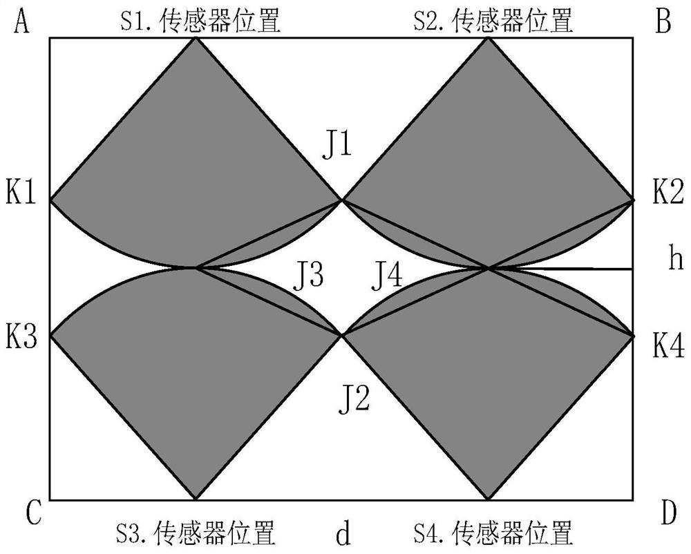
The invention relates to the field of transformer partial discharge ultrasonic positioning, in particular to a method for positioning a partial discharge position in a transformer based on a sensor. Comprising the following steps: 1) establishing a three-dimensional coordinate system of a transformer, and arranging a plurality of ultrasonic sensors on the transformer; 2) arranging HFCT (High Frequency Current Transformer) sensors at any position on the transformer, acquiring data through ultrasonic sensors, and selecting sensor data of the ultrasonic sensor which firstly receives an ultrasonic signal from the ultrasonic sensors as resolving data; and 3) according to the time reference measured by the FHCT sensor, resolving the resolving data to obtain the position of the partial discharge point. According to the method, the positioning precision of the ultrasonic sensor for positioning the partial discharge point in the transformer is improved, the propagation characteristics of the ultrasonic signal in the transformer are further analyzed, a mathematical model is accurately established, and the positioning precision is improved.

Description

technical field [0001] The invention relates to the field of ultrasonic positioning and detection of transformer partial discharge, in particular to a sensor-based positioning method for partial discharge position in a transformer. Background technique [0002] The transformer is one of the most important equipment in the national energy transmission system. The stable operation of the transformer affects the safe operation of the entire power grid and is also related to the safety of the national energy strategy. Due to the high-voltage operating environment of the transformer itself, any minor fault of the transformer can easily lead to a major accident if it is not solved in time. In fact, over the years, the failure of the transformer to be eliminated in time has caused serious consequences such as power outages and casualties in the power grid. Among them, the partial discharge fault of the outlet device on the valve side of the transformer is a common and more harmful...

Claims


Application Information

Patent Timeline
Patent Type & Authority Applications(China)
IPC IPC(8): G01R31/12
CPCG01R31/1209G01R31/1227
Inventor 曹成张剑峰闫睿智李金忠王琳孙建涛程涣超张书琦遇心如吴超赵晓宇张荐张磊周家斌常延龙
Owner SIFANG-TBEA INTELLIGENT ELECTRICAL CO LTD
Learn More