
Electronic device

A technology of electronic equipment and camera components, applied in the field of electronic equipment, can solve the problems of small dispensing size, difficulty in ensuring the consistency of the fixed position of the secondary camera, and poor consistency of the optical effect of the dual camera module, so as to achieve the effect of ensuring the relative positional relationship

Inactive Publication Date: 2017-09-22
LENOVO (BEIJING) LTD
View PDF4 Cites 6 Cited by
  • Summary
  • Abstract
  • Description
  • Claims
  • Application Information

AI Technical Summary

Problems solved by technology

[0003] However, the two cameras of the dual camera module in the prior art are fixed together by a ring bracket, or are formed by welding two cameras on a printed circuit board. Defects
Among them, the dual-camera module in the form of a ring bracket has a small dispensing size in the height direction of the camera, and the position of the main camera is poorly consistent during mass production, making it difficult to ensure the consistency of the fixed position of the sub-camera when dispensing and fixing. As a result, the optical consistency of the mass-produced dual-camera modules is poor; for dual-camera modules that share a printed circuit board, after the main camera is soldered on the printed circuit board, it is difficult to solder the sub-camera on the printed circuit board. Guarantee, resulting in a low yield rate during mass production, and at the same time, the overall strength of this form of dual camera module is low, and it is easy to be damaged during transportation

Method used


Image

  • Electronic device
  • Electronic device
  • Electronic device

Examples


Embodiment Construction

[0042] In order to further explain the technical means and effects of the present invention to achieve the intended purpose of the invention, the specific implementation, structure, features and effects of the electronic equipment proposed according to the present invention will be described in detail below in conjunction with the accompanying drawings and preferred embodiments. The description is as follows. In the following description, different "one embodiment" or "embodiment" do not necessarily refer to the same embodiment. Furthermore, the particular features, structures, or characteristics of one or more embodiments may be combined in any suitable manner.

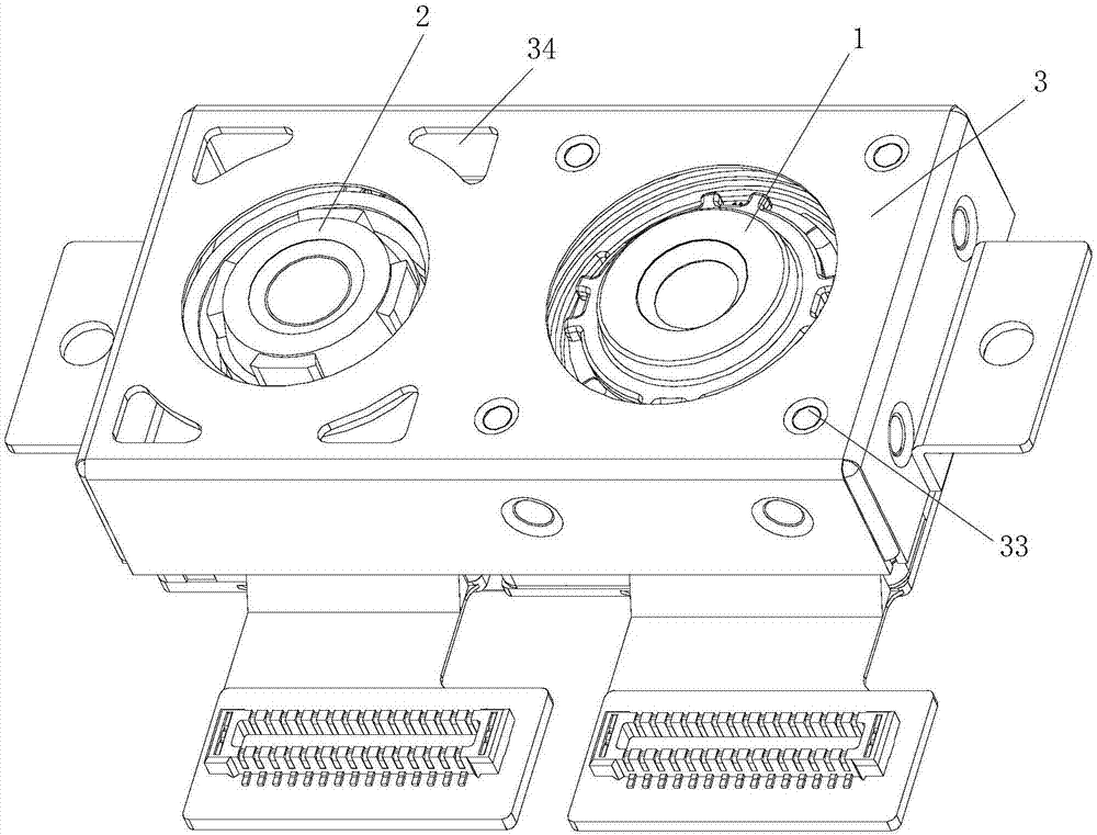
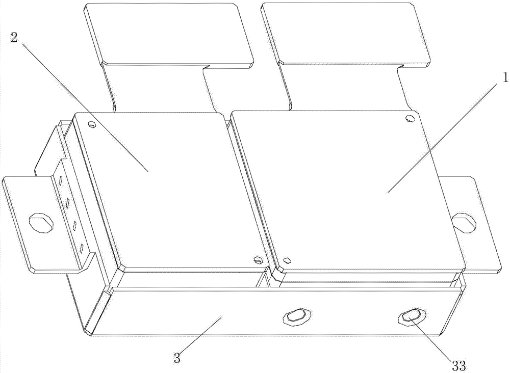
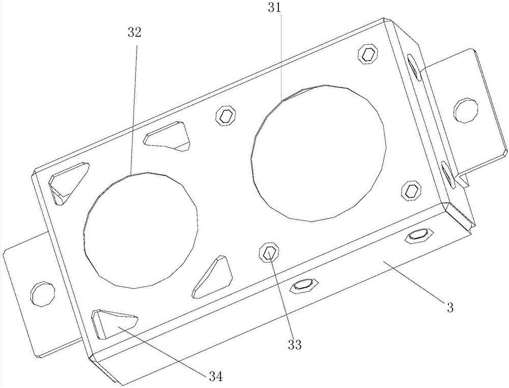
[0043] Such as Figure 1-4As shown, an electronic device proposed by an embodiment of the present invention includes: a first camera assembly 1, a second camera assembly 2, and a metal bracket 3; the metal bracket 3 is used to accommodate and fix the first camera assembly 1 and the second camera assembly Two camera...


PUM


Abstract

The invention discloses an electronic device and relates to the field of the electronic device. The main technical scheme provided by the invention is that the electronic device comprises a first camera assembly, a second camera assembly and a metal holder. The metal holder is used for containing and fixing the first camera assembly and the second camera assembly. The first camera assembly and the second camera assembly are fixed together according to first arrangement. The metal holder is equipped with a first through hole and a second through hole. The first through hole is used for exposing a first lens of the first camera assembly. The second through hole is used for exposing a second lens of the second camera assembly. The metal holder is fixedly mounted in the shell of the electronic device, so the first camera assembly and the second camera assembly are fixedly mounted in the shell. The main purpose is that the two camera assemblies in the electronic device are assembled together through the metal holder and then are mounted in the shell of the electronic device. The effect of improving the strength and facilitating the positioning is achieved.

Description

technical field [0001] The invention relates to the field of electronic equipment, in particular to an electronic equipment. Background technique [0002] At present, commonly used electronic devices such as mobile phones, tablet computers or laptops are generally provided with cameras, and users can use the cameras on these electronic devices to take pictures. Dual cameras are set on the electronic device, and pictures are taken through the dual camera module. [0003] However, the two cameras of the dual camera module in the prior art are fixed together by a ring bracket, or are formed by welding two cameras on a printed circuit board. Defects. Among them, the dual-camera module in the form of a ring bracket has a small dispensing size in the height direction of the camera, and the position of the main camera is poorly consistent during mass production, making it difficult to ensure the consistency of the fixed position of the sub-camera when dispensing and fixing. As a...

Claims


Application Information

Patent Timeline
Patent Type & Authority Applications(China)
IPC IPC(8): H04N5/225
CPCH04N23/51H04N23/54H04N23/50H04N23/57H04N23/55
Inventor 魏晓峰王瑜陈杰峰
Owner LENOVO (BEIJING) LTD
Learn More