Implant acid etching fixture device

An implant and acid etching technology, which is applied in the fields of implantology, medical science, dentistry, etc., can solve the problems of not being able to etch the annular smooth surface, and achieve the effects of avoiding acid corrosion, improving tooling efficiency, and fast tooling

Pending Publication Date: 2017-09-26
CHENGDU BESMILE BIOTECH
View PDF10 Cites 2 Cited by
  • Summary
  • Abstract
  • Description
  • Claims
  • Application Information

AI Technical Summary

Problems solved by technology

[0003] Do not acid-etch the annular smooth surface (2) during the etching process, because the annular smooth

Method used


Image

  • Implant acid etching fixture device
  • Implant acid etching fixture device
  • Implant acid etching fixture device

Examples


Embodiment Construction

[0019] The present invention will be further described below in conjunction with accompanying drawing, protection scope of the present invention is not limited to the following:

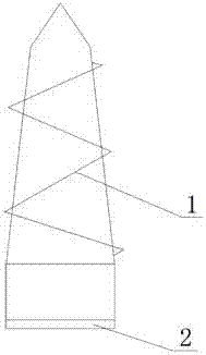
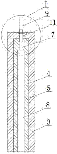
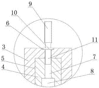
[0020] Such as Figure 2~5 As shown, the implant acid-etching tooling device includes a ceramic outer cylinder 3, an inner cylinder 4 and a cross-shaped threaded rod. The bottom of the ceramic outer cylinder 3 is provided with a step hole 5, and the top of the ceramic outer cylinder 3 is provided with a connecting step hole. 5, the centerline of the annular groove 6 coincides with the centerline of the step hole 5, the inner cylinder 4 is inserted into the large hole of the step hole 5, and the top of the inner cylinder 4 is provided with a threaded hole A7, The bottom of the inner cylinder 4 is provided with a threaded hole B8. The cross-shaped threaded rod is composed of an upper threaded head 9, a ring member 10 and a lower threaded head 11 connected in sequence. The nominal diameter of the upper ...


PUM


Abstract

The invention discloses an implant acid etching fixture device which comprises a ceramic outer cylinder (3), an inner cylinder (4) and a cross-shaped threaded rod, wherein a step hole (5) is formed in the bottom of the ceramic outer cylinder (3); an annular groove (6) communicating with the step hole (5) is formed in the top of the ceramic outer cylinder (3); the inner cylinder (4) is inserted in a big hole of the step hole (5); a threaded hole A (7) is formed in the top of the inner cylinder (4); a threaded holes B (8) is formed in the bottom of the inner cylinder (4); the cross-shaped threaded rod is composed of an upper thread head, a ring-shaped part (10) and a lower thread head (11) which are connected in sequence; the lower thread head (11) penetrates through the annular groove (6) and a small hole of the step hole (5) in sequence and is in threaded connection with the threaded hole A (7); and the ring-shaped part (10) is arranged in the annular groove (6) and is pressed at the bottom of the annular groove (6). The implant acid etching fixture device disclosed by the invention has the beneficial effects of being compact in structure, effectively protecting an annular plain face, rapidly clamping an implant, and being simple to operate.

Description

technical field [0001] The invention relates to the technical field of oil stain acid etching on implants, in particular to an implant acid etching tooling device. Background technique [0002] Oral implants are also known as dental implants, also known as artificial tooth roots, such as figure 1 Shown is a schematic diagram of the structure of the implant, which has screw teeth (1) on the outside and internal threads on the inside, and a ring-shaped smooth surface (2) on the periphery of the head, which is connected to the denture. The implant is surgically implanted into the upper or lower jaw of the tooth-missing part of the human body, and after the surgical wound is healed, the screw teeth (1) are integrated with the upper or lower jaw. Before the implant is used, since there are oil stains and impurities attached to the surface, it is necessary to acid-etch the outer surface of the implant with acid solution to remove the oil stains and impurities. [0003] During th...

Claims


Application Information

Patent Timeline
IPC IPC(8): A61C8/00
CPCA61C8/0087
Inventor 鄢新章刘福祥万乾炳冯崇敬王昌健刘谋山
Owner CHENGDU BESMILE BIOTECH
Why Eureka
Try Eureka