Al technical title is built by PatSnap Al team. It summarizes the technical point description of the patent document.
A technology of heat sink and solder pin is applied in the field of assembly machines for automatic assembly of pin type heat sinks, which can solve problems such as low efficiency and occupation of labor.
Inactive Publication Date: 2014-12-24
宁海县雁苍山电力建设有限公司 +3
View PDF7 Cites 0 Cited by
Summary
Abstract
Description
Claims
Application Information
AI Technical Summary
This helps you quickly interpret patents by identifying the three key elements:
Problems solved by technology
Method used
Benefits of technology
Problems solved by technology
[0002] As an accessory part of electronic products, heat sinks are used in more and more fields. With the continuous increase of electronic products, the demand for heat sinks is also increasing. The demand for products targeted by the present invention can reach 300 million per year. One, and the number shows an increasing trend every year. At present, people mostly use manual methods to realize its assembly, which takes up a lot of labor and is very inefficient. Therefore, there is an urgent need for an automatic assembly machine in the market, but there is no such machine in the market.
Method used
Image
Click on the blue label to locate the original text in one second.
Reading with bidirectional positioning of images and text.
Examples
Embodiment Construction
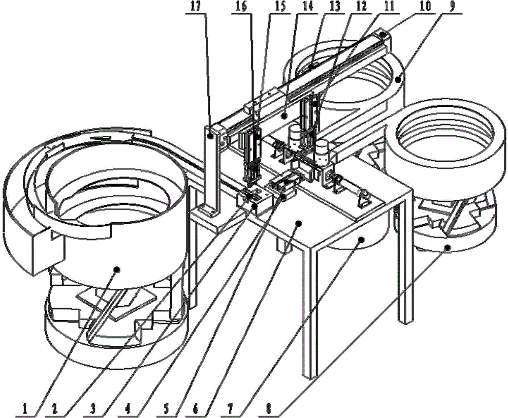
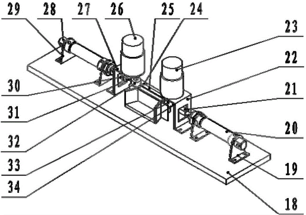
[0009] Such as figure 1 , figure 2 Shown: a heat sink assembly machine for inserting welding pins, which is composed of a first heat sink vibrator, a first heat sink 2, a temporary storage bin 3, a push cylinder pad 4, a push cylinder 5, a first bracket 6, and a finished product Material silo 7, first welding needle vibration plate 8, second welding needle vibration plate 9, rodless cylinder 10, first vertical cylinder 11, first air claw 12, second bracket 13, connector 14, second Vertical cylinder 15, second air claw 16, third support 17, base plate 18, small cylinder first support 19, first small cylinder 20, first connecting block 21, first DC motor fixing plate 22, first DC motor 23 , clamp 24, second heat sink 25, second DC motor 26, second DC motor fixing plate 27, second small cylinder 28, small cylinder second bracket 29, second connecting block 30, second pin 31, the second The second insertion welding is for the middle block 32, the first insertion welding is for ...
PUM
Abstract
The invention relates to an insert welding pin radiating fin assembly machine, which structurally comprises a radiating fin vibrating device, a first radiating fin, a temporary storage bin, a pushing air cylinder cushion block, a pushing air cylinder, a first support, a finished product bin, a first insert welding pin vibrating plate, a second insert welding pin vibrating plate, a rodless air cylinder, a first vertical air cylinder, a first air claw, a second support, a connecting piece, a second vertical air cylinder, a second air claw, a third support, a base plate, a small air cylinder first support, a first small air cylinder, a first connecting block, a first direct-current motor fixing plate, a first direct-current motor, a fixture, a second radiating fin, a second direct-current motor, a second direct-current motor fixing plate, a second small air cylinder, a small air cylinder second support, a second connecting block, a second insert pin, a second insert welding pin centering block, a first insert welding pin centering block, and a first insert pin. The device can be used for realizing quick assembly of insert welding pins and radiating fins, and has the characteristics of high efficiency, labor saving and the like.
Description
technical field [0001] The invention relates to an assembly machine for pin-welding heat sinks, in particular to an assembly machine for automatically assembling a pin-type heat sink by using a vibrator, a cylinder, a hand grip, and the like. Background technique [0002] As an accessory part of electronic products, heat sinks are used in more and more fields. With the continuous increase of electronic products, the demand for heat sinks is also increasing. The demand for products targeted by the present invention can reach 300 million per year. One, and the number shows an increasing trend every year. At present, people mostly use manual methods to realize its assembly, which takes up a lot of labor and is very inefficient. Therefore, there is an urgent need for an automatic assembly machine in the market, but there is no such machine in the market. . Contents of the invention [0003] In view of the above shortcomings, the present invention provides a heat sink assembly...
Claims
Application Information
Patent Timeline
Application Date:The date an application was filed.
Publication Date:The date a patent or application was officially published.
First Publication Date:The earliest publication date of a patent with the same application number.
Issue Date:Publication date of the patent grant document.
PCT Entry Date:The Entry date of PCT National Phase.
Estimated Expiry Date:The statutory expiry date of a patent right according to the Patent Law, and it is the longest term of protection that the patent right can achieve without the termination of the patent right due to other reasons(Term extension factor has been taken into account ).
Invalid Date:Actual expiry date is based on effective date or publication date of legal transaction data of invalid patent.