Concrete mixing equipment for bridge building

A mixing equipment and concrete technology, applied in clay preparation equipment, chemical instruments and methods, cement mixing equipment, etc., can solve problems such as inconvenient handling, low mixing efficiency, uneven mixing, etc.

Active Publication Date: 2017-09-26
舟山市丰翔预拌混凝土有限公司
View PDF7 Cites 13 Cited by
  • Summary
  • Abstract
  • Description
  • Claims
  • Application Information

AI Technical Summary

Problems solved by technology

[0006] In order to overcome the disadvantages of low mixing efficiency, inconvenient handling and uneven mixing in general concrete mixing equipment, the technical problem to be solved by the invention is to provide a concrete mixer for bridge construction with high mixing efficiency, convenient handling and uniform mixing. equipment

Method used


Image

  • Concrete mixing equipment for bridge building
  • Concrete mixing equipment for bridge building
  • Concrete mixing equipment for bridge building

Examples


Embodiment 1

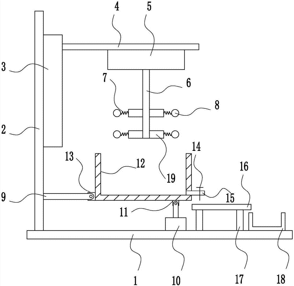
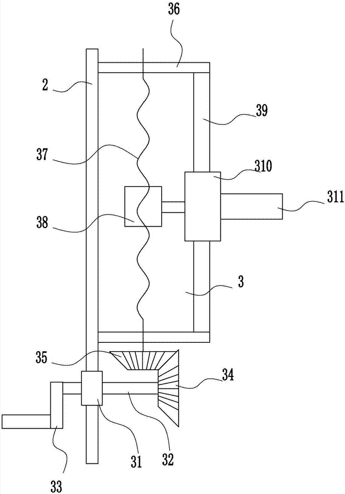
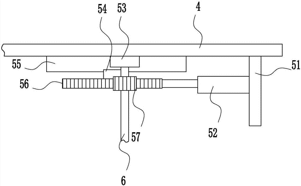
[0037] A concrete mixing plant for bridge construction, such as Figure 1-6 As shown, it includes a bottom plate 1, a left frame 2, a lifting device 3, a first mounting plate 4, a rotating device 5, a second rotating shaft 6, a spring 7, a steel ball 8, a second connecting rod 9, a shaking device 10, a first fixing Block 11, stirring frame 12, second fixed block 13, electric control valve 14, discharge pipe 15, conveying device 16, support 17, collecting frame 18 and stirring blade 19, left frame 2 is welded on the left side of bottom plate 1 top, left A lifting device 3 is arranged on the upper right side of the frame 2, a first mounting plate 4 is connected to the upper right side of the lifting device 3, a rotating device 5 is arranged in the middle of the bottom of the first mounting plate 4, and a second rotating shaft 6 is connected in the middle of the bottom of the rotating device 5, The bottom of the second rotating shaft 6 is evenly welded with stirring blades 19, th...

Embodiment 2

[0039] A concrete mixing plant for bridge construction, such as Figure 1-6 As shown, it includes a bottom plate 1, a left frame 2, a lifting device 3, a first mounting plate 4, a rotating device 5, a second rotating shaft 6, a spring 7, a steel ball 8, a second connecting rod 9, a shaking device 10, a first fixing Block 11, stirring frame 12, second fixed block 13, electric control valve 14, discharge pipe 15, conveying device 16, support 17, collecting frame 18 and stirring blade 19, left frame 2 is welded on the left side of bottom plate 1 top, left A lifting device 3 is arranged on the upper right side of the frame 2, a first mounting plate 4 is connected to the upper right side of the lifting device 3, a rotating device 5 is arranged in the middle of the bottom of the first mounting plate 4, and a second rotating shaft 6 is connected in the middle of the bottom of the rotating device 5, The bottom of the second rotating shaft 6 is evenly welded with stirring blades 19, th...

Embodiment 3

[0042] A concrete mixing plant for bridge construction, such as Figure 1-6 As shown, it includes a bottom plate 1, a left frame 2, a lifting device 3, a first mounting plate 4, a rotating device 5, a second rotating shaft 6, a spring 7, a steel ball 8, a second connecting rod 9, a shaking device 10, a first fixing Block 11, stirring frame 12, second fixed block 13, electric control valve 14, discharge pipe 15, conveying device 16, support 17, collecting frame 18 and stirring blade 19, left frame 2 is welded on the left side of bottom plate 1 top, left A lifting device 3 is arranged on the upper right side of the frame 2, a first mounting plate 4 is connected to the upper right side of the lifting device 3, a rotating device 5 is arranged in the middle of the bottom of the first mounting plate 4, and a second rotating shaft 6 is connected in the middle of the bottom of the rotating device 5, The bottom of the second rotating shaft 6 is evenly welded with stirring blades 19, th...


PUM


Abstract

The invention relates to mixing equipment, in particular to concrete mixing equipment for bridge building. The concrete mixing equipment for bridge building aims at achieving the technical effects that stirring efficiency is high; carrying is convenient to conduct; and stirring is conducted uniformly. The concrete mixing equipment for bridge building comprises a base plate, a left rack, a lifting device, a first mounting plate, a rotating device, a second rotating shaft, springs, steel balls, a second connecting rod, a shaking device, a first fixing block and the like. The left rack is welded to the left side of the top of the base plate. The lifting device is arranged above the right side of the left rack. The position above the right side of the lifting device is connected with the first mounting plate. The rotating device is arranged in the middle of the bottom of the first mounting plate. According to the concrete mixing equipment, a worker rocks a rocking rod to control the lifting device, positions of stirring vanes are controlled manually, and the effect is better; and the rotating device is controlled to work, so that the stirring vanes are driven to conduct stirring.

Description

technical field [0001] The invention relates to a mixing device, in particular to a concrete mixing device for bridge construction. Background technique [0002] Bridges generally refer to structures erected on rivers, lakes and seas to allow vehicles and pedestrians to pass smoothly. In order to adapt to the modern high-speed development of the transportation industry, bridges are also extended to buildings that cross mountain streams, poor geology or meet other transportation needs to make traffic more convenient. A bridge is generally composed of a superstructure, a substructure, a support and ancillary structures. The superstructure is also called a bridge span structure, which is the main structure for crossing obstacles; the substructure includes abutments, piers and foundations; Or the force transmission device installed at the supporting place of the bridge abutment; the auxiliary structures refer to the bridge head board, conical slope protection, bank protection, ...

Claims


Application Information

Patent Timeline
Patent Type & Authority Applications(China)
IPC IPC(8): B28C5/16
Inventor 冯瑞芳
Owner 舟山市丰翔预拌混凝土有限公司
Why Eureka
Try Eureka