Pipe bending machine and gear transmission device thereof

A technology of gear transmission and input gear, applied in transmission parts, belts/chains/gears, mechanical equipment, etc., can solve the problems of unsatisfactory product quality, low stability of manufacturing accuracy, insufficient bending accuracy, etc. The effect of ensuring parallelism, improving stability, and improving accuracy

Pending Publication Date: 2017-09-26
浙江和良智能装备有限公司
View PDF9 Cites 9 Cited by
  • Summary
  • Abstract
  • Description
  • Claims
  • Application Information

AI Technical Summary

Problems solved by technology

Although the use of chain transmission can meet the requirements of the pipe bender for transmitting heavy loads with a large span, the chain will be severely worn due to long-term use, resulting in insufficient pipe bending precision and resulting in product quality that cannot meet the requirements, that is, The stability of product manufacturing accuracy is low

Method used


Image

  • Pipe bending machine and gear transmission device thereof
  • Pipe bending machine and gear transmission device thereof
  • Pipe bending machine and gear transmission device thereof

Examples


Embodiment 1

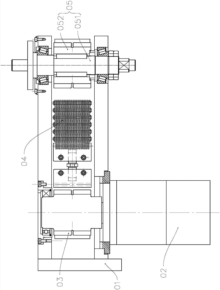
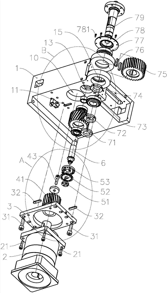
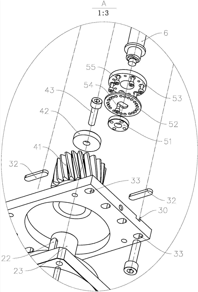
[0036] see Figure 2 to Figure 7 , the pipe bender of the present invention includes a frame 1 and a power unit installed on the frame 1, a gear transmission device and a pipe bending device (not shown in the figure), and the frame 1 is a cavity structure with an installation chamber 100, The power device includes a reducer 2; the gear transmission is a three-stage gear transmission, including an input unit, a transition unit and an output unit; the input unit includes a reducer mounting plate 31, an input gear 41 and an adjustment assembly; the transition unit includes an eccentric shaft 6, The transition gear 57 and the adjustment locking mechanism; the output unit includes an output shaft 79 and an output gear 75 .

[0037] The reducer 2 is fixed on the reducer mounting plate 3 through four fixing bolts 21, and the input gear 41 is set on the output shaft 23 of the reducer 2 through the flat key 22 to form a limit for the movement of the input gear 41 in the circumferential...

Embodiment 2

[0059] As an illustration of Embodiment 2 of the present invention, only the differences from Embodiment 1 above will be described below.

[0060] see Figure 11 to Figure 13 , by setting the pin hole 170 on the side wall plate 17 of the frame 1, in this embodiment, the adjustment locking mechanism also includes a locking pin 61 and a locking screw 62, and the outer port of the pin hole 170 is provided with a locking Screw 62 matches the screw thread, and the inner end surface of anti-loosening pin 81 is formed with the arc-shaped extruding surface 810 that matches with the side wall surface of the mounting shaft portion 61 of eccentric shaft 6, and the arc of anti-loosening pin 81 is made by locking screw 82. The shaped extrusion surface 810 extrudes the side wall surface of the mounting shaft portion 61 to form a friction fit surface to assist in locking the rotation angle position of the eccentric shaft 6 .

Embodiment 3

[0062] As an illustration of Embodiment 3 of the present invention, only the differences from Embodiment 1 above will be described below.

[0063] The above-mentioned adjustment and locking mechanism can be replaced by a subdivision mechanism to form the first gap adjustment mechanism, that is, the requirements for adjusting, indexing and positioning locking of the rotation angle of the eccentric shaft can be realized by using the subdivision mechanism.


PUM


Abstract

The invention relates to a pipe bending machine and a gear transmission device thereof, and belongs to the technical field of pipe machining treatment. The gear transmission device comprises a rack and an output unit, a transitional unit, an input unit and a clearance adjustment mechanism which are mounted on the rack, wherein the output unit comprises an output gear; the input unit comprises an input gear; the transitional unit comprises a transitional gear simultaneously meshing with the output gear and the input gear; the clearance adjustment mechanism comprises a first clearance adjustment mechanism for adjusting a side clearance between the transitional gear and the output gear and a second clearance adjustment mechanism for adjusting a side clearance between the input gear and the transitional gear; the first clearance adjustment mechanism comprises an eccentric shaft and an adjustment and locking mechanism for adjusting a rotating angle of the eccentric shaft and locking the position of the rotating angle of the eccentric shaft; and the transitional gear is arranged on the eccentric shaft in a rotatable sleeving manner. The pipe bending machine consisting of the gear transmission device is high in product manufacturing precision and stability, and the gear transmission device can be widely applied to equipment such as the pipe bending machine.

Description

technical field [0001] The invention relates to pipe material processing equipment, in particular to a gear transmission device and a pipe bending machine constructed with the gear transmission device. Background technique [0002] The patent document with the notification number CN86208918U discloses a rotary pipe bending machine head, which includes a pipe bending device and a transmission device that transmits the power of the power device to the pipe bending device. The pipe bending device includes a pipe bending die, a support wheel and a pipe clamp Tightening device; the transmission device is a rack and pinion transmission device, including a gear arranged coaxially with the pipe bending die and a rack meshed with the gear, and the rack is not permanently connected to the power device. The transmission device with a rack and pinion structure can transmit the torque and movement required by the pipe bending die over a large span, but its structure is so large that the ...

Claims


Application Information

Patent Timeline
Patent Type & Authority Applications(China)
IPC IPC(8): F16H57/12B21D7/16
CPCF16H57/12B21D7/16F16H2057/125
Inventor 张良李良有
Owner 浙江和良智能装备有限公司
Why Eureka
Try Eureka