
Battery pack welding sealing method

A technology for welding packaging and battery packs, which is applied to battery pack components, circuits, electrical components, etc., can solve problems such as low welding efficiency, many processes, and virtual welding, and achieve improved welding efficiency, high automation, and guaranteed welding efficiency Effect

Active Publication Date: 2017-09-26
湖南澳莱雅生物科技有限公司
View PDF5 Cites 0 Cited by
  • Summary
  • Abstract
  • Description
  • Claims
  • Application Information

AI Technical Summary

Problems solved by technology

[0003] (1) It is necessary to manually weld the tabs together, and it is also necessary to weld the lead wires to the solder joints, which requires many procedures and low welding efficiency;
[0004] (2) Because many solder joints and wires need to be soldered on a small PCB board; it is easy to cause false soldering, and the soldering reliability is not high
[0005] (3) With the traditional welding method, it is difficult to make regular solder joints, and the appearance of the power output side of the entire battery pack is not beautiful, which affects the appearance of the product
[0006] (4) Manual welding is used, and the efficiency is low

Method used


Image

  • Battery pack welding sealing method
  • Battery pack welding sealing method
  • Battery pack welding sealing method

Examples


Embodiment 1

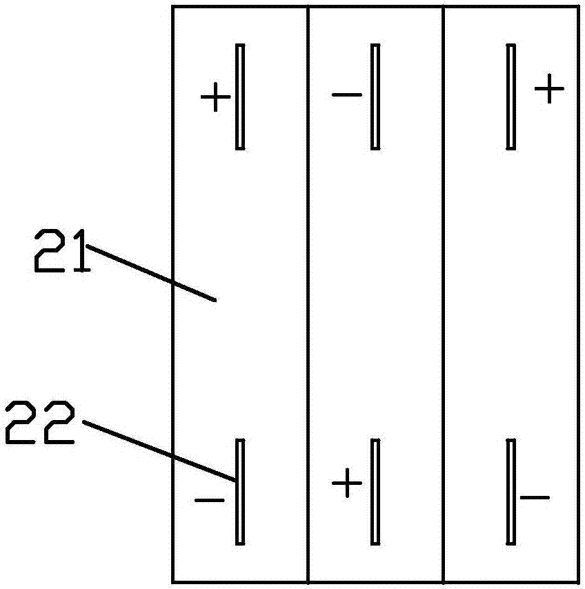
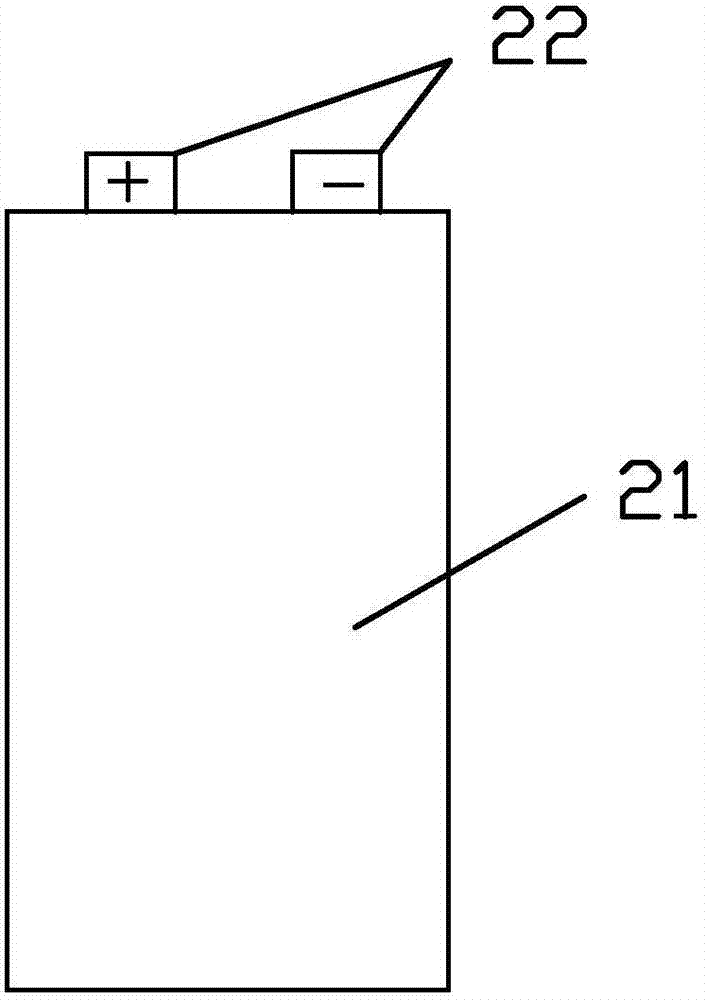
[0112] Embodiment 1: as Figure 3-5 , a battery module based on a mouth-type connector, including a battery pack and a connector; the battery pack is formed by stacking three batteries 21;

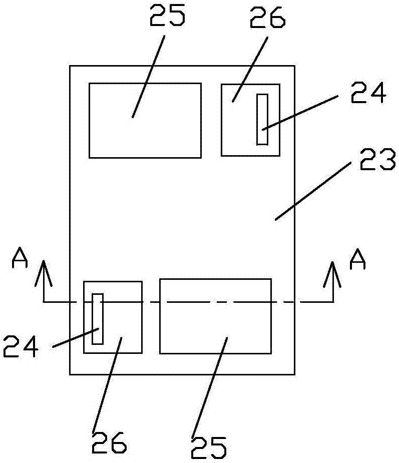
[0113] The connecting seat includes a seat body; 4 recesses are arranged on the top of the seat body 23;

[0114] Welding depressions, or called accommodating grooves; here, the two tabs of the battery pack are welded together by soldering or the tabs are welded together with the lead-out end of the battery pack's main electrodes.

[0115] The relationship between the number n of welding depressions and the number N of batteries is: n=N+1; specifically, 2 total power outlets are welded with depressions, and N-1 battery cell electrodes are welded with depressions; (total power supply terminals The welding recesses are used to lead out the general electrodes of the battery pack (ie the overall positive and negative electrodes).

[0116] Among the welding depressions, two welding depression...

Embodiment 2

[0123] Embodiment 2: as Figure 6-8 ; On the basis of Embodiment 1, a battery pack socket 32 ​​for accommodating the battery pack or the end of the battery pack is provided on the upper side of the base body (that is, on the same side as the recessed portion).

Embodiment 3

[0124] Embodiment 3: as Figure 9-13 , On the basis of Embodiment 1, the difference from Embodiment 1 is that a pin 33 is inserted into the bottom of the welding recess of the lead-out end of the general power supply. The pin is connected with a power supply auxiliary plug-in terminal 30 through a wire, which is generally used as a mainboard power supply terminal. The power supply auxiliary plug-in end can be a socket or a plug. way of manufacturing.


PUM


Abstract

The invention discloses a battery pack welding sealing method which comprises the following steps: 1, putting a connecting base into a sealing jig, namely at a welding station, conveying the connecting base into the sealing jig on a conveyer belt through an automatic conveying mechanism; 2, injecting molten welding tin, namely injecting molten welding tin into a welding concave part by using an injection mechanism; 3, inserting a battery pack, namely inserting electrode lugs of a battery into the concave part manually or by using a manipulator, and soaking the electrode lugs into the molten welding tin; 4, cooling the battery at a cooling station. The battery pack welding sealing method is easy to implement and high in welding and sealing efficiency.

Description

technical field [0001] The invention relates to a method for welding and packaging a battery pack. Background technique [0002] When battery packs are connected in series and in parallel, the positive and negative electrodes of different battery cells are connected by wires, or the positive and negative electrodes of different battery cells are connected by a special PCB board. At the same time, the PCB board also plays the role of isolation to prevent battery cells The short circuit of the body; but when using wires or PCB connections, there are the following problems: [0003] (1) It is necessary to manually weld the tabs together, and it is also necessary to weld the lead wires to the solder joints, which requires many procedures and low welding efficiency; [0004] (2) Because many solder joints and wires need to be soldered on a small PCB board; it is easy to cause false soldering, and the soldering reliability is not high. [0005] (3) With the traditional welding m...

Claims


Application Information

Patent Timeline
Patent Type & Authority Applications(China)
IPC IPC(8): H01M2/10
CPCH01M50/20Y02E60/10
Inventor 唐艳红许欢谭哲谭正英
Owner 湖南澳莱雅生物科技有限公司
Learn More