Circuit breaker

A line protection and switching technology, which is applied to the protection switch, the parts of the protection switch, the operation/release mechanism of the protection switch, etc., to achieve the effect of simple replacement

Active Publication Date: 2017-09-26
J 斯姆尔科利
View PDF6 Cites 2 Cited by
  • Summary
  • Abstract
  • Description
  • Claims
  • Application Information

AI Technical Summary

Problems solved by technology

Here, this arrangement consumes about 0.5‰ of the electrical power

Method used


Image

  • Circuit breaker
  • Circuit breaker
  • Circuit breaker

Examples


Embodiment Construction

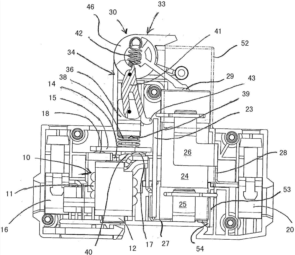
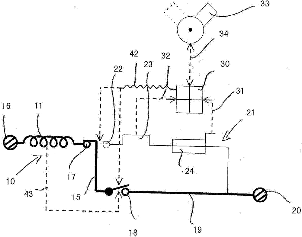
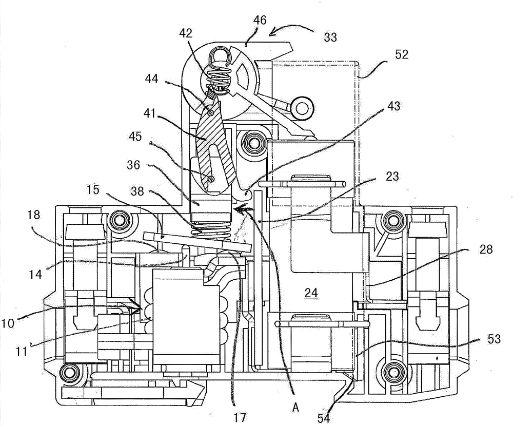
[0046] as in Figure 1A and 1B As shown in , the line protection switch according to the first embodiment of the present invention has an electromagnetic release 10 with a coil 11 and an armature 12 which acts on a contact plate 15 via a striker 14 . The coil 11 is connected via its one end to the terminal 16 and via its other end to the first contact 17 . In the switched-on state, the contact 17 is connected via a contact plate 15 to a second contact 18 on which a corresponding contact relative to the first contact 17 is formed, which is formed by a main current path 19. The electrical conductor element is connected to a further terminal 20 . In the ON state, the main current path 19 is connected in series with the coil 11 of the electromagnetic release 10 and thus connects the two terminals 16 , 20 of the circuit breaker according to the invention together with the coil 11 . In trouble-free operation, terminals 16 and 20 are connected exclusively via a series circuit consi...


PUM


Abstract

The invention relates to a circuit breaker having two parallel current paths each with a contact point (15, 18; 15, 22) which, as the main and secondary current paths (19, 21), are connected, via a contact device (15, 17, 18, 22), in series with a coil (11) of a magnetic trip (10), the armature (12) of which, in the event of a fault, opens the contact point (15, 18) of the main current path (19) which is formed exclusively only by the series circuit of the contact device (15, 17, 18) with the coil (11). In order to provide a further circuit breaker which, in the case of energy losses which are minimized during normal continuous operation, prevents the formation of an arc when the circuit is interrupted in the event of a fault and therefore also largely prevents contacts from burning away, provision is made, in the case of a circuit breaker according to the invention, for an interrupter and trip insert (24) to be arranged in the secondary current path (21), which insert, in the event of a short circuit, interrupts the secondary current path and trips a switching lock (30) to open and secure the contact device (15, 17, 18, 22).

Description

technical field [0001] The invention relates to a circuit breaker with two parallel-conducted current paths, which each have a contact point and which pass as primary and secondary current paths through a connection between a contact device and an electromagnetic release. The coils are respectively connected in series. Background technique [0002] From DE 10 2011 016 933 A1 such a circuit breaker is known, in which the armature of the electromagnetic release opens the contact point of the main current path via a plunger or striker in the event of a fault, so that the current is now Flow only through the secondary current path and its contact points. In this case, the contact points in the primary current path are opened without arcing, since the contact points are short-circuited by the secondary current path. In the event of a short-circuit current, the contact point of the secondary current path, which is designed as an arc contact, is opened in a shock-like manner by a...

Claims


Application Information

Patent Timeline
IPC IPC(8): H01H71/12H01H71/02H01H85/30
CPCH01H71/0228H01H71/122H01H85/306H01H1/20H01H71/52
Inventor J·斯姆尔科利
Owner J 斯姆尔科利
Why Eureka
Try Eureka