Environment-friendly building solid waste treatment equipment

A solid waste and processing equipment technology, applied in grain processing, solid separation, dispersed particle filtration, etc., can solve the problems of inconvenient recycling, waste of resources, air pollution, etc., and achieve the effect of improving resource utilization and gas cleanliness

Inactive Publication Date: 2017-09-29
童贤波
0 Cites 12 Cited by

AI-Extracted Technical Summary

Problems solved by technology

[0003] On construction sites, a large amount of construction rubble or cement block solid waste is usually produced. There are usually a large amount of metal building material scraps in these wastes, which are inconvenient to recyc...

Method used

When the present invention uses, construction solid waste enters cabinet 1 from feeding hole 2 by feeder plate 4 under the effect of baffle plate 7, and solid waste is when passing through feeder plate 4, the metallic solid in material Under the action of the magnetic plate 5, it is fixed on the material guide plate 4 to realize the separation of part of the metal solids. Most of the metal solids enter the cabinet 1 with the stones, and the stones are crushed under the action of the crushing roller 9 and fall to...

Abstract

The invention discloses an environment-friendly construction solid waste treatment equipment, which comprises a machine case, a purification box and a base. The top wall of the inner chamber of the machine case is provided with a feeding hole, and the left side of the top opening of the feeding hole is fixedly connected with a baffle plate, and the feeding The right side of the opening at the top of the hole is equipped with a material guide plate that matches the baffle plate. The inner cavity of the cabinet is equipped with a crushing roller and a screen. The outer circular surface of the crushing roller is evenly equipped with several crushing teeth. There is a discharge hole in the middle, the bottom of the chassis is connected to the discharge pipe, the other side wall of the chassis is connected to the exhaust pipe, the other end of the exhaust pipe is connected to the bottom of the purification box, and the bottom of the chassis is uniform There are several supporting legs; the present invention ensures that the metal solids in the construction solid waste are completely separated by setting magnetic plates and screening nets, and the double layers are sequentially screened, so as to realize the recyclable utilization of resources and improve the utilization rate of resources; The exhaust gas is purified layer by layer through the purification box to ensure that the discharged gas is clean and pollution-free.

Application Domain

Technology Topic

Image

  • Environment-friendly building solid waste treatment equipment
  • Environment-friendly building solid waste treatment equipment
  • Environment-friendly building solid waste treatment equipment

Examples

  • Experimental program(1)

Example Embodiment

[0017] The technical solution of this patent will be described in further detail below in conjunction with specific embodiments.
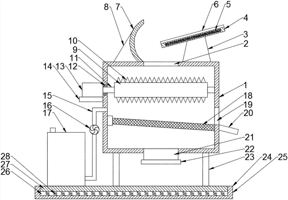
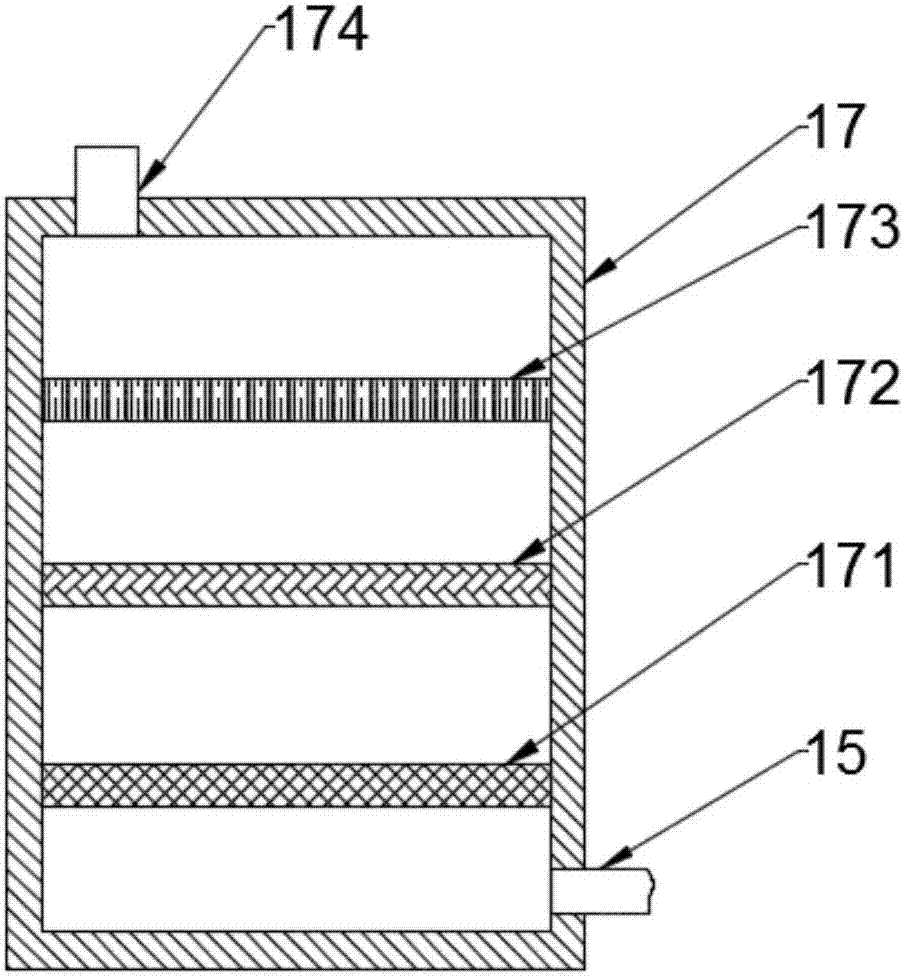
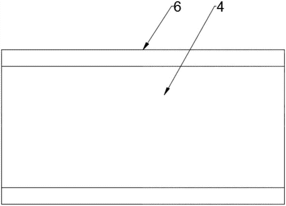
[0018] See Figure 1~3 , An environmentally friendly construction solid waste treatment equipment, comprising a cabinet 1, a purification tank 17, and a base 24. The top wall of the inner cavity of the cabinet 1 is provided with a feed hole 2, and the top opening of the feed hole 2 is fixed on the left side Connected to the baffle 7, the baffle 7 is an arc-shaped plate, the left end of the baffle 7 is provided with a reinforcing rib 8, and the right side of the top opening of the feed hole 2 is provided with a matching baffle 7 The material guide plate 4, the material guide plate 4 is arranged obliquely, the material guide plate 4 is fixed on the top of the chassis 1 by the support 3, the material guide plate 4 is provided with a magnetic plate 5, and the magnetic plate 5 is selected from natural Made of magnets, the front and rear sides of the guide plate 4 are symmetrically provided with baffles 6; the inner cavity of the cabinet 1 is provided with a crushing roller 9 and a screen 18, and the crushing roller 9 is set above the screen 18 to crush The outer surface of the roller 9 is uniformly provided with a number of crushing teeth 10, the crushing roller 9 is rotatably connected to the chassis 1 through a rotating shaft 11, one end of the rotating shaft 11 passes through the side wall of the chassis 1 and is fixedly connected to the motor shaft of the motor 13 The rotating shaft 11 is rotatably connected to the side wall of the chassis 1 through the bearing 12. The motor 13 is fixed on the support plate 14, and one end of the support plate 14 is fixed on the side wall of the chassis 1. The middle of the wall is provided with a discharge hole 19, the screen 18 is arranged obliquely, the lowest end of the screen 18 corresponds to the discharge hole 19, and the outer end of the discharge hole 19 is provided with a deflector 20, the The baffle 20 is arranged obliquely, the bottom end of the chassis 1 is connected to a discharge pipe 21, the bottom end of the discharge pipe 21 is hinged with a sealing cover 22, and the other side wall of the chassis 1 is connected to exhaust The other end of the exhaust pipe 15 is connected to the bottom end of the clean box 17 through the pipe 15. The exhaust pipe 15 is provided with a fan 16 and the top end of the clean box 17 is connected through an exhaust pipe 174. The clean box The inner cavity of 17 is sequentially provided with an activated carbon filter layer 173, a HEPA high efficiency filter 172 and a dust filter 171 from top to bottom. The bottom end of the chassis 1 is evenly provided with a number of legs 23, and the chassis 1 passes through the legs. 23 is fixedly connected to the base 24; the base 24 includes a bottom plate 25, a shock-absorbing plate 27, and a shock-absorbing component 28. The top of the bottom plate 25 is provided with a cavity 26, and the cavity 26 is provided with a shock-absorbing plate 27 , The bottom end of the damping plate 27 is fixedly connected to the bottom wall of the cavity 26 through the damping assembly 28, the damping plate 27 and the cavity 26 are slidingly connected, the top surface of the damping plate 27 and the top end of the bottom plate 25 The surface is flush, and the bottom ends of all the legs 23 are fixedly connected to the top end of the shock-absorbing plate 27.
[0019] When the present invention is used, the solid waste of construction enters the cabinet 1 from the feed hole 2 through the guide plate 4 under the action of the baffle 7, and when the solid waste passes through the guide plate 4, the solid metal in the material is on the magnetic plate It is fixed on the guide plate 4 under the action of 5 to realize the separation of part of the metal solids. Most of the metal solids enter the cabinet 1 with the stones. The stones are crushed under the action of the crushing roller 9 and fall together with the metal solids in the screening. On the screen 18, crushed stones pass through the screen 18 and are discharged from the discharge pipe 21. The metal solids are discharged from the discharge hole 19 along the screen 18; the gas generated during the crushing process enters the purification box 17 and passes through the dust filter 171 , HEPA high efficiency filter 172 and activated carbon filter layer 173 filter to ensure that the discharged air is clean and environmentally friendly.
[0020] The preferred embodiments of this patent are described in detail above, but this patent is not limited to the above-mentioned embodiments, and within the scope of knowledge possessed by those of ordinary skill in the art, it is also possible to make various decisions without departing from the purpose of this patent. Kind of change.

PUM

no PUM

Description & Claims & Application Information

We can also present the details of the Description, Claims and Application information to help users get a comprehensive understanding of the technical details of the patent, such as background art, summary of invention, brief description of drawings, description of embodiments, and other original content. On the other hand, users can also determine the specific scope of protection of the technology through the list of claims; as well as understand the changes in the life cycle of the technology with the presentation of the patent timeline. Login to view more.

Similar technology patents

Classification and recommendation of technical efficacy words

  • Improve resource utilization
  • Gas clean
Why Eureka
Try Eureka