Ion beam adjusting device

A current regulation and ion beam technology, applied in the direction of discharge tubes, electrical components, circuits, etc., can solve the problems of uneven magnetic field in the height direction, adverse effects of sample uniformity, unfavorable post-beam transmission and control, etc., to achieve cost Low, simple structure and reliable effect

Active Publication Date: 2017-09-29
东莞嘉拓日晟智能科技有限公司
View PDF6 Cites 2 Cited by
  • Summary
  • Abstract
  • Description
  • Claims
  • Application Information

AI Technical Summary

Problems solved by technology

In this way, after the ribbon beam passes through the magnet, due to the unevenness of the dipole magnet in the height direction, the cross-sectional shape of the ribbon beam will change from a straight line to a meniscus, which is not conducive to the later transmission and control of the beam. It will also have a certain adverse effect on the uniformity of the injected sample.
In addition, the magnetic field between the pole heads of the dipole magnet with this structure is not uniform in the height direction, which cannot meet the requirements of beam transmission and injection

Method used


Image

  • Ion beam adjusting device
  • Ion beam adjusting device
  • Ion beam adjusting device

Examples


Embodiment 1

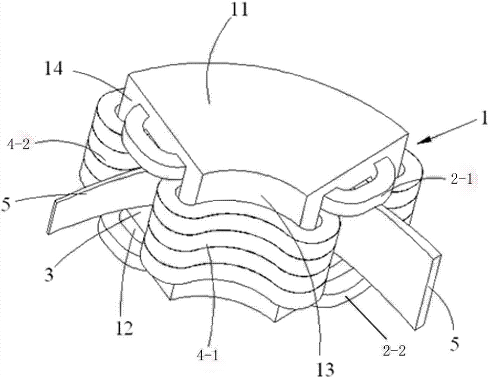
[0032] Such as image 3 and 4 As shown, the present invention provides an ion beam adjustment device, which can keep the cross-sectional shape of the ribbon beam in a straight line when the beam passes through by adjusting the current magnitude and direction of the coil, and can adjust The uniformity of the beam flow in the height direction.

[0033] The ion beam current regulating device comprises an iron core 1, a pole head, a first coil 2-1 and a second coil 2-2, and the iron core 1 comprises an upper iron core block 11, a lower iron core block 12, a front iron core Block 13 and rear core block 14, the pole head includes an upper pole head 6-1 and a lower pole head 6-2, the front and rear ends of the upper core block 11 and the lower core block 12 respectively pass through the front The iron core block 13 is connected to the rear iron core block 14, and the upper pole head 6-1 and the lower pole head 6-2 are attached to the upper iron core block 11 and the lower iron core...

Embodiment 2

[0048] This embodiment is substantially the same as Embodiment 1, except that the third coil 4-1 sleeved on the front core block 13 and the fourth coil sleeved on the rear core block 14 are The quantity is 2; the radians of the front core block and the rear core block are both 3π / 4.

Embodiment 3

[0050] This embodiment is substantially the same as Embodiment 1, except that the third coil 4-1 sleeved on the front core block 13 and the fourth coil sleeved on the rear core block 14 are The quantity is 50; the radians of the front core block and the rear core block are both π / 4.


PUM


Abstract

The invention mainly belongs to the technical field of ion beam adjusting device, and specifically relates to an ion beam adjusting device. The ion beam adjusting device comprises an iron core, pole heads, a first coil and a second coil, wherein the iron core comprises an upper iron core block, a lower iron core block, a front iron core block and a rear iron core block; the front ends and the rear ends of the upper iron core block and the lower iron core block are connected with the front iron core block and the rear iron core block respectively; and the inner side faces of the upper iron core block, the lower iron core block, the front iron core block and the rear iron core block are defined together to form a through hole. The ion beam adjusting device also comprises third coils stacked on the front iron core block in sequence in a sleeving manner and fourth coils stacked on the rear iron core block in sequence in the sleeving manner. According to the ion beam adjusting device disclosed by the invention, the cross section shape of a strip-shaped beam can be maintained to be the shape of a straight line when the beam passes through the device, and the uniformity of the beam in the height direction can be adjusted, so that the requirements of beam transmission and injection are met.

Description

technical field [0001] The invention mainly belongs to the technical field of ion beam adjustment devices, and in particular relates to an ion beam adjustment device, which can keep the cross-sectional shape of the ribbon beam in a straight line when the beam passes through, and can adjust the uniformity of the beam in the height direction . Background technique [0002] Common secondary magnets (or ion beam adjustment devices) currently on the market such as figure 1 and figure 2 As shown, it includes an iron core 1' and two coils 2', the iron core 1' includes an upper iron core block 11' and a lower iron core block 12', the front and back of the upper iron core block 11' and the lower iron core block 12' The two ends are respectively connected by the front core block 13' and the rear core block 14', and the upper core block 11', the lower core block 12', the front core block 13' and the rear core block 14' form a connection hole 3', two coils 2' are respectively embedd...

Claims


Application Information

Patent Timeline
Patent Type & Authority Applications(China)
IPC IPC(8): H01J37/141
CPCH01J37/141
Inventor 钱锋
Owner 东莞嘉拓日晟智能科技有限公司
Why Eureka
Try Eureka