
Device and method for speed reduction of a container flow in a container treatment plant

A technology for processing facilities and containers, which is applied in liquid processing, transportation and packaging, bottle filling, etc., and can solve problems such as insufficient compensation

Active Publication Date: 2017-09-29
KRONES AG
View PDF13 Cites 1 Cited by
  • Summary
  • Abstract
  • Description
  • Claims
  • Application Information

AI Technical Summary

Problems solved by technology

Especially when a single-lane container stream is fanned out, for example by a sorting device, into several container streams and then the containers of the respective container streams are assembled into bundles, large pitch differences can occur which can only be Insufficient compensation with individual distribution worms

Method used


Image

  • Device and method for speed reduction of a container flow in a container treatment plant
  • Device and method for speed reduction of a container flow in a container treatment plant

Examples


Embodiment Construction

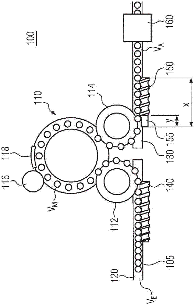
[0044] figure 1 An exemplary embodiment of a container treatment plant 100 with a transport device for changing the pitch of a container flow is shown. Here, the transport device connects the rotary machine 110 with the shrink-fit unit 160 in this non-limiting embodiment. Along the rotary machine 110, the containers 105 are processed at a machine speed V preset by the processing speed of a labeling device 116 arranged at the periphery of the rotary machine 110. M turnover. The label applied to the container 105 by the labeling device 116 is pressed onto the container after passing through the pressing station 118 .

[0045] In order to be able to convey the containers 105 from an incoming container stream in which the containers are transported one by one on a conveyor belt 120 to the rotary machine 110, the container processing plant 100 has an incoming star wheel 112 and an upstream distribution worm with increasing pitch 140. The upstream distributing screw 140 accommod...


PUM


Abstract

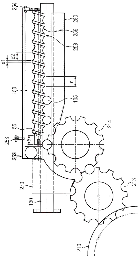
The invention discloses a device and method for speed reduction of a container flow in a container treatment plant. The invention relates to a device and a method for reducing the speed of a container flow in a container treatment plant. According to the invention, a conveying device (100) for speed reduction of a container stream (105) in a container treatment plant (110) comprises at least one infeed worm (150), said infeed worm having a recess (155) in its infeed portion.

Description

technical field [0001] The present invention relates to a transport device and method for decelerating or pitching a flow of containers using a distribution worm in a container processing facility. Background technique [0002] In container treatment plants, containers, such as bottles, cans or the like, are treated in one or more successive process steps. A subunit of a container processing plant, a so-called block, can comprise, for example, a filling unit for filling containers, a labeling device, an inspection unit and / or a packaging unit for forming and packaging container bundles. In this case, the containers to be processed are usually transported and processed in different processing units as a continuous flow of containers at different speeds, the different speeds being predetermined by the design and technology of the respective processing units. [0003] In order to guarantee the continuity of the entire container flow through the subunits, the containers are the...

Claims


Application Information

Patent Timeline
Patent Type & Authority Applications(China)
IPC IPC(8): B65G33/04B65G47/30
CPCB65G33/04B65G47/30B65G2201/0244B65G2201/0235B65G47/846B67C7/0046
Inventor 哈拉尔德·菲舍尔于尔根·斯泰莫
Owner KRONES AG
Learn More