Floating Mechanism of Money Detecting Device and Money Detecting Device

A technology of floating mechanism and floating shaft, which is applied in the authenticity inspection of banknotes, instruments, handling coins or valuable banknotes, etc. It can solve the problems of single component cost increase, equipment failure, processing cost and maintenance cost increase, etc., to achieve The effect of reducing processing costs and reducing maintenance costs

Active Publication Date: 2019-10-11
SHENZHEN YIHUA COMP
View PDF5 Cites 0 Cited by
  • Summary
  • Abstract
  • Description
  • Claims
  • Application Information

AI Technical Summary

Problems solved by technology

When the position of the banknote in the channel deviates, it will affect the accuracy of detection
In addition, since there are many detection points and different locations need to be installed, installation and maintenance are more difficult
[0003] The floating shaft of the existing banknote verification module uses a pair of torsion springs to ensure that the floating shaft slides up and down in the designed track groove; under normal circumstances, the bending arms of the left and right torsion springs act on the outside of the rib bearing, while In the actual working process of the banknote verification module, the bending arms of the torsion springs on both sides of the floating shaft may have a position away from the rib bearing, which means that the torsion spring structure realizes the floating effect of the floating shaft. At the position of the mechanism, the magnetic mechanism cannot accurately collect the magnetic information of the banknotes, and it will also cause the banknotes to be jammed at the position of the magnetic mechanism, which will cause equipment failure;
[0004] The contact between the torsion spring and the rib bearing is point contact, and the design of the bending arm is limited by the position of the rib of the rib bearing, so it should not be too long. There will be differences, which are reflected on the outside of the rib bearings on both sides of the floating shaft due to different force points, resulting in inconsistent elastic forces on the left and right sides of the floating shaft, and at this time the position of the action point of the torsion spring cannot be adjusted;
[0005] In addition, the torsion spring is easy to deform due to the wire diameter (generally designed to be 0.8-1mm), which is also a problem in the logistics link. It is necessary to strictly control the control, which will cause the cost of a single component to increase;
[0006] The left and right torsion springs have a symmetrical structure, that is, the left and right torsion springs are two parts and cannot be replaced. Two parts need to be managed, resulting in increased processing costs and maintenance costs

Method used


Image

  • Floating Mechanism of Money Detecting Device and Money Detecting Device
  • Floating Mechanism of Money Detecting Device and Money Detecting Device
  • Floating Mechanism of Money Detecting Device and Money Detecting Device

Examples


Embodiment Construction

[0040] In order to make the purpose, technical solution and advantages of the present application clearer, the present application will be further described in detail below in conjunction with the accompanying drawings and embodiments. It should be understood that the specific embodiments described here are only used to explain the present application, and are not intended to limit the present application.

[0041] It should be noted that when an element is referred to as being “fixed on” or “disposed on” another element, it can be directly on the other element or there may be an intervening element at the same time. When an element is referred to as being "connected to" another element, it can be directly connected to the other element or intervening elements may also be present.

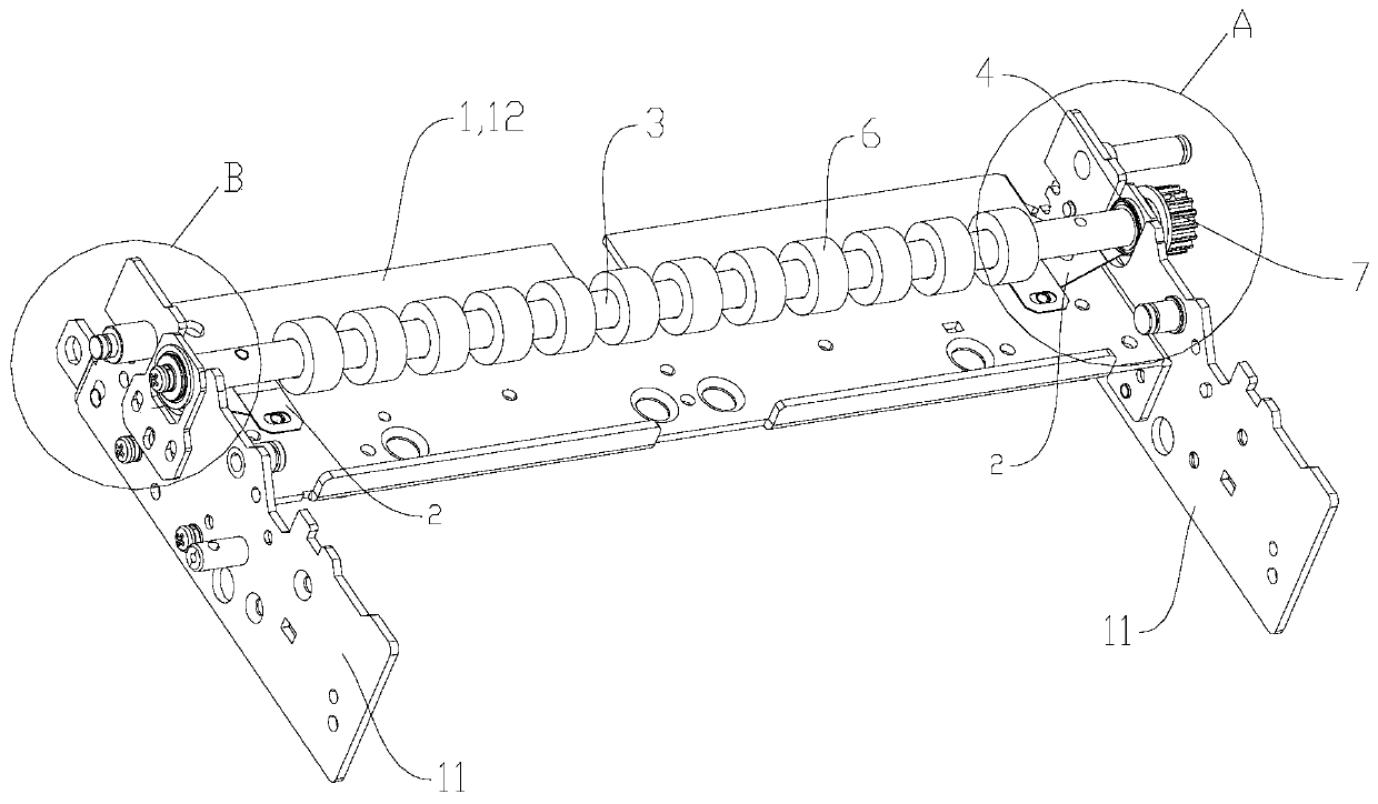
[0042] Such as figure 1As shown, the floating mechanism of the banknote detection device provided by the embodiment of the present application includes a bracket 1 and a floating shaft 3 that can ...


PUM


Abstract

A bank note verification floating mechanism and a bank note verifier. The floating mechanism comprises a support (1), two elastic strips (2), and a floating shaft (3). A flanged bearing (4) sleeves each of the left and right ends of the floating shaft (3). The support (1) comprises two support plates (11) parallel to each other and a fixed plate (12) disposed between the two support plates (11). Each end of the floating shaft (3) is mounted on a corresponding support plate (11) by means of a corresponding flanged bearing. One end of each elastic piece is fixed on the fixed plate (12), and the other end presses against one side of a corresponding flanged bearing (4) close to the fixed plate (12). The bank note verifier comprises a magnetic sensor (5) and the floating mechanism. A floating roller (6) sleeves on the floating shaft (3), a conveyor belt pulley (7) is disposed at one end of the floating shaft (3). The bank note verifier of the invention is capable of collecting magnetic data of bank notes stably and reliably.

Description

technical field [0001] The invention belongs to the technical field of financial equipment, and in particular relates to a floating mechanism of a banknote checking device and a banknote checking device. Background technique [0002] In the existing financial recycling machine equipment, there is a banknote checking module. The banknote checking module has a banknote transfer channel, and there are rollers above and below the banknote transfer channel. In order to avoid paper money wear and tear, one of the rollers needs to be installed on the floating axis. There are scattered detection points arranged between the rollers. When the banknotes are driven by the rollers and pass through the scattered detection points, each detection point detects the designated position of the banknotes to judge whether it is a counterfeit banknote. When the position of the banknote in the channel deviates, it will affect the accuracy of detection. In addition, since there are many detectio...

Claims


Application Information

Patent Timeline
Patent Type & Authority Patents(China)
IPC IPC(8): G07D7/04
CPCG07D7/04
Inventor 王敏灵
Owner SHENZHEN YIHUA COMP
Why Eureka
Try Eureka