
Cutters for internal burrs of straight seam steel pipes

A steel pipe and straight seam technology, which is applied in the field of pipe fitting cleaning equipment, can solve the problems of reducing the service life of steel pipes, reducing strength, and reducing the stability of steel pipes in use, so as to reduce the probability of stress fracture, strengthen support stability, and improve transportation efficiency. Effect

Active Publication Date: 2019-09-03
CHENGDU ZHIRONG ZHICHUANG INTPROP MANAGEMENT CO LTD
View PDF8 Cites 0 Cited by
  • Summary
  • Abstract
  • Description
  • Claims
  • Application Information

AI Technical Summary

Problems solved by technology

However, after the partial welding of the steel pipe is completed, the weld seam is directly exposed to the air. Due to the difference between the air temperature and the temperature of the weld seam itself, the weld seam will directly change from high temperature to low temperature. The strength of the steel itself reduces the stability of the steel pipe, and in severe cases it will directly cause the weld seam of the steel pipe to be de-welded; and a certain amount of burrs will be generated inside and outside the steel pipe near the weld seam during welding, which makes the flow rate of the fluid in the pipe drop when the steel pipe is in use. , and the protrusions at the weld are easily corroded, which leads to a decrease in the overall strength of the weld and reduces the service life of the steel pipe; traditional internal burr removal equipment mainly focuses on the solder residue and protrusions around the weld and the weld However, the solder residue and protrusions scattered to other parts of the inner wall of the steel pipe during welding are not cleaned thoroughly

Method used


Image

  • Cutters for internal burrs of straight seam steel pipes
  • Cutters for internal burrs of straight seam steel pipes

Examples


Embodiment 1

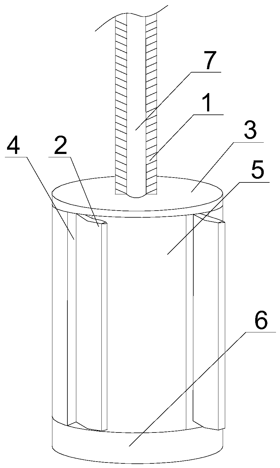
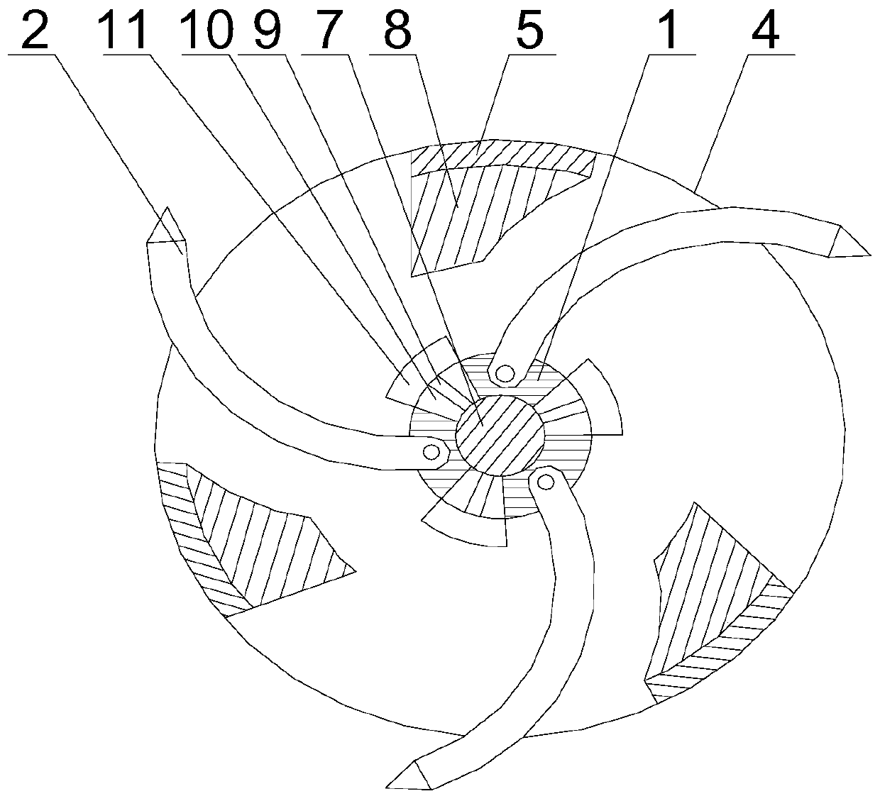
[0020] Such as figure 1 and figure 2 As shown, this embodiment includes a cylinder 5, a central shaft 1, a fixed plate 3 and a base 6, the fixed plate 3 seals the upper end of the cylinder 5 connected thereto, and the base 6 is fixedly connected to the lower end of the cylinder 5 A screw 7 is fixed in the middle of the upper surface of the base 6, the central shaft 1 moves through the middle of the fixed plate 3 and then extends downward, and a threaded through hole is opened in the middle along the axial direction of the central shaft 1, corresponding to the threaded through hole The matched screw rod 7 extends to the upper end of the cylinder body 5 after penetrating the threaded through hole, and a plurality of arc-shaped cutting pieces 2 are arranged on the central shaft 1, and a plurality of the cutting pieces 2 are hinged to the central shaft 1 and are evenly distributed on the On the outer peripheral wall of the central shaft 1, and along the radial direction of the c...


PUM


Abstract

The invention discloses a cutter for burrs in a straight-seam steel pipe. The cutter comprises a cylinder, a central shaft, a fixing plate and a base, wherein a threaded rod is fixed at the middle of the upper surface of the base; after movably penetrating through the middle of the fixing plate, the central shaft extends downward; a threaded through hole is formed in the middle of the central shaft; after penetrating through the threaded through hole, the threaded rod extends towards the upper end of the cylinder; a plurality of cutting sheets are arranged on the central shaft and hinged with the central shaft; a plurality of fan-shaped holes are formed in the outer wall of the central shaft; a plurality of connecting rods are arranged on the outer wall of the threaded rod; after penetrating through the fan-shaped holes, the connecting rods extend outward; stop blocks are fixed in the extension sections of the connecting rods; a plurality of regulating holes are formed in the outer circumferential wall of the cylinder; and limiting blocks are arranged on the inner circumferential wall of the cylinder. The cutter has the advantages that after the cylinder is rotated for several times, the protrusion height of dirt on the inner wall of the steel pipe is lowered; after the threaded rod is rotated again, the parts, extending outward, of the cutting sheets are increased, thereby enlarging the cleaning radii of the cutting sheets and achieving the secondary cleaning operation on the inner wall of the steel pipe; and accordingly, the dirt is thoroughly cleaned up.

Description

technical field [0001] The invention relates to pipe fitting cleaning equipment, in particular to a cutter for internal burrs of straight seam steel pipes. Background technique [0002] When welding steel pipes, in order to ensure a good welding effect, the welding head and the steel pipe to be welded are generally placed in a semi-closed box to facilitate the introduction of protective gas and avoid sparks splashing around during welding. However, after the partial welding of the steel pipe is completed, the weld seam is directly exposed to the air. Due to the difference between the air temperature and the temperature of the weld seam itself, the weld seam will directly change from high temperature to low temperature. The strength of the steel itself reduces the stability of the steel pipe, and in severe cases it will directly cause the weld seam of the steel pipe to be de-welded; and a certain amount of burrs will be generated inside and outside the steel pipe near the wel...

Claims


Application Information

Patent Timeline
Patent Type & Authority Patents(China)
IPC IPC(8): B23D79/04
Inventor 吴光武
Owner CHENGDU ZHIRONG ZHICHUANG INTPROP MANAGEMENT CO LTD
Learn More