Laser marking method based on CCD navigation positioning

A laser marking method and navigation and positioning technology, which is applied in the field of laser marking, can solve the problems of customers without products and limit the application range of laser marking, and achieve the effects of low cost of use, increased use range, and precise positioning and marking

Active Publication Date: 2017-10-03
GUANGDONG ZHENGYE TECH
View PDF5 Cites 18 Cited by
  • Summary
  • Abstract
  • Description
  • Claims
  • Application Information

AI Technical Summary

Problems solved by technology

The general CCD positioning marking needs to be based on the product CAD drawing, but in actual production, customers often do n

Method used


Image

  • Laser marking method based on CCD navigation positioning
  • Laser marking method based on CCD navigation positioning
  • Laser marking method based on CCD navigation positioning

Examples


Embodiment Construction

[0052] The following will clearly and completely describe the technical solutions in the embodiments of the present invention in conjunction with the accompanying drawings in the embodiments of the present invention. Obviously, the described embodiments are only some of the embodiments of the present invention, not all of them. Based on the embodiments of the present invention, all other embodiments obtained by persons of ordinary skill in the art without making creative efforts belong to the protection scope of the present invention.

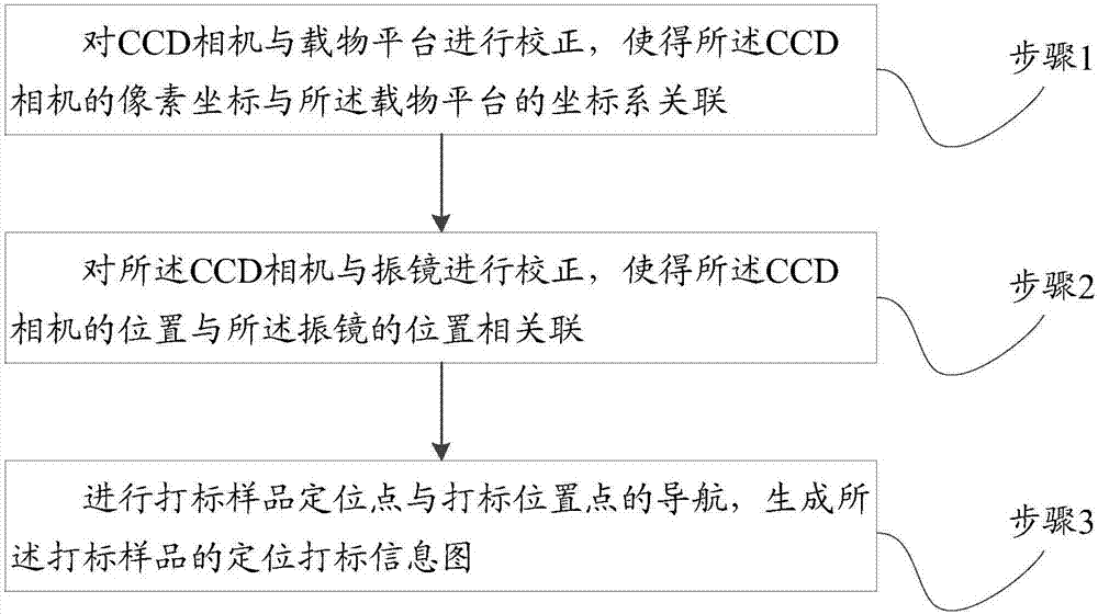
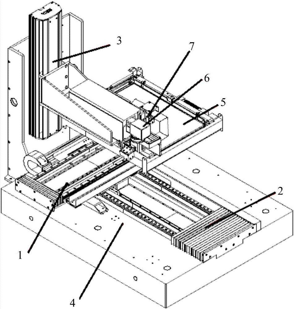
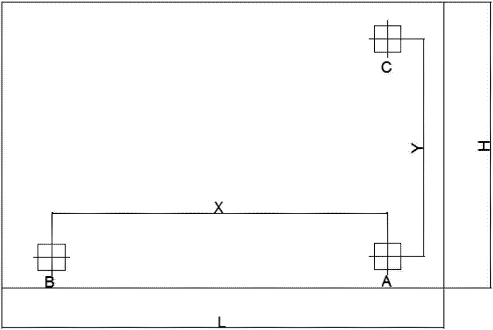
[0053] Please refer to Figure 1 to Figure 5 , figure 1 A schematic flow chart of the steps of a specific implementation of the laser marking method based on CCD navigation and positioning provided by the embodiment of the present invention; figure 2 A schematic diagram of the mechanical structure of the marking machine in the laser marking method based on CCD navigation and positioning provided by the embodiment of the present invention; i...


PUM

PropertyMeasurementUnit
Overlap widthaaaaaaaaaa

Abstract

The invention discloses a laser marking method based on CCD navigation positioning. The laser marking method comprises the steps that (1) a CCD camera and an object carrying platform are corrected, and therefore a pixel coordinate of the CCD camera is related to a coordinate system of the object carrying platform; (2) the CCD camera and an oscillating mirror are corrected, and therefore the position of the CCD camera is related to the position of the oscillating mirror; and (3) navigation of a marking sample positioning point and a marking position point is carried out, and a positioning marking information pattern of a marking sample is generated. The CCD camera, the object carrying platform and the oscillating mirror are corrected, and therefore the pixel coordinate of the CCD camera and the coordinate system of the object carrying platform are related, and the CCD camera and the position of the oscillating mirror are related; then navigation of the marking sample positioning point and the marking position point is carried out, the positioning marking information pattern of the marking sample is generated, and therefore the positioning marking information pattern achieves accurate positioning marking under the condition that no sample CAD pattern positioning marking information exist due to the similar sample positioning marking information CAD patterns, and the using scope of an existing CAD pattern machine is improved.

Description

technical field [0001] The invention relates to the technical field of laser marking, in particular to a laser marking method based on CCD navigation and positioning. Background technique [0002] Laser marking is one of the largest application fields of laser processing. Laser marking is a kind of chemical reaction that uses high-energy-density laser to partially irradiate the workpiece to vaporize the surface material or undergo a color change, thereby leaving a permanent mark. method. Laser marking can print various characters, symbols and patterns, etc., which has special significance for product anti-counterfeiting and product traceability. [0003] With the rapid development of domestic industry 2020, foreign industry 4.0 and the Internet of Things, factories pay more and more attention to product traceability and management, such as raw material procurement, product process and technology, product batches, manufacturers, production dates, product destinations and oth...

Claims


Application Information

Patent Timeline
IPC IPC(8): B41M5/24
CPCB41M5/24
Inventor 刘林徐地明赵建滔肖磊林克徐地华
Owner GUANGDONG ZHENGYE TECH
Why Eureka
Try Eureka