
Non-independent suspension frame

A non-independent suspension and frame technology, applied in suspension, elastic suspension, transportation and packaging, etc., can solve the problem of poor load-carrying capacity and anti-rolling capacity of the vehicle, wear of leaf spring and steering knuckle, and wheel steering angle Small and other problems, to achieve the effect of improving driving safety, improving the overall rigidity, and increasing the steering angle

Active Publication Date: 2017-10-03
TSINGHUA UNIV
View PDF6 Cites 2 Cited by
  • Summary
  • Abstract
  • Description
  • Claims
  • Application Information

AI Technical Summary

Problems solved by technology

However, the suspension leaf springs involved in the above-mentioned patents are multi-leaf composite leaf springs, and relative motion is allowed between the leaf springs and the steering knuckle, which may easily cause serious wear of the leaf springs and steering knuckles during the wheel beating process, and even wheel damage may occur under extreme loads. side fall accident
[0005] To sum up, the vehicle suspension in the prior art has the problems of poor load-carrying capacity and anti-rolling capacity of the whole vehicle, and the problem that the wheel steering angle is small

Method used


Image

  • Non-independent suspension frame
  • Non-independent suspension frame
  • Non-independent suspension frame

Examples


Embodiment Construction

[0029] The following will clearly and completely describe the technical solutions in the embodiments of the present invention with reference to the accompanying drawings in the embodiments of the present invention. Obviously, the described embodiments are only some, not all, embodiments of the present invention. Based on the embodiments of the present invention, all other embodiments obtained by persons of ordinary skill in the art without making creative efforts belong to the protection scope of the present invention.

[0030] The purpose of the present invention is to provide a non-independent suspension to solve the problems in the prior art.

[0031] In order to make the above objects, features and advantages of the present invention more comprehensible, the present invention will be further described in detail below in conjunction with the accompanying drawings and specific embodiments.

[0032] The present invention provides a non-independent suspension, such as Figure...


PUM


Abstract

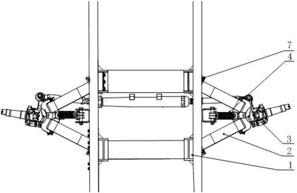
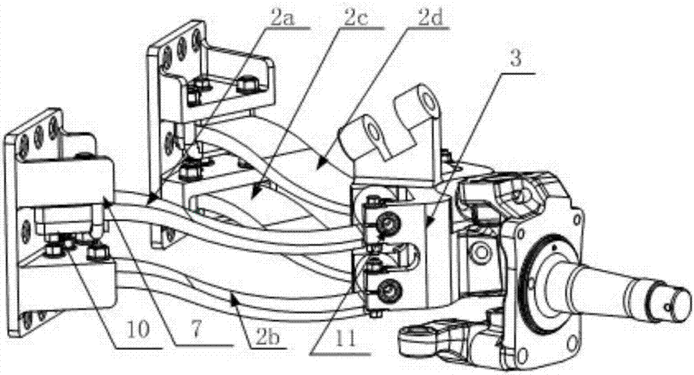
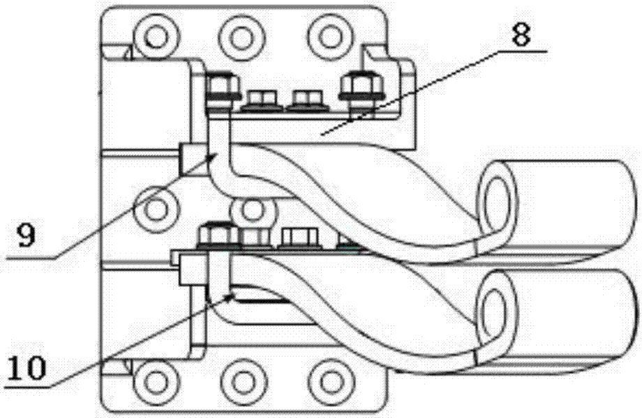
The invention discloses a non-independent suspension frame comprising two obliquely-arranged plate spring assemblies which are symmetrically arranged on the two sides of a vehicle frame. Each obliquely-arranged plate spring assembly comprises four obliquely-arranged plate springs, wherein the two obliquely-arranged plate springs are located on the tops of the other two obliquely-arranged plate springs; one ends of the obliquely-arranged plate springs are connected with the vehicle frame; the other ends of the obliquely-arranged plate springs are connected with wheel hub connecting members; every two corresponding obliquely-arranged plate springs located on the tops and the vehicle frame form a triangular structure in an enclosed mode; and the other two corresponding obliquely-arranged plate springs located at the bottoms and the vehicle frame form a triangular structure in an enclosed mode. The non-independent suspension frame further comprises spring shock absorbers, and the two ends of the spring shock absorbers are connected with the vehicle frame and the wheel hub connecting members correspondingly and located on the upper portions of the obliquely-arranged plate spring assemblies. According to the non-independent suspension frame, application of the obliquely-arranged plate springs and the spring shock absorbers is combined, the carrying capacity and the lateral-tilting resistance capacity of a vehicle can be improved, wheel positioning parameters are improved, the steering angle is increased, the bearing center distance is increased, tire internally-tilting is avoided, and abnormal friction of tires is reduced.

Description

technical field [0001] The invention relates to the technical field of vehicle suspension, in particular to a non-independent suspension. Background technique [0002] The car suspension is to ensure that the wheels and the frame (or body) have an elastic connection and be able to carry the load of the car, ease the impact, adjust the position of the car body during driving, etc., directly determines the operating stability and driving stability of the car Wait. The structural feature of the non-independent suspension is that the wheels on both sides are connected through an integral axle, and the wheels and the axle are connected to the frame through elastic components. This structure has large bearing capacity, high reliability, simple structure and low production cost. low merit. [0003] At present, the front axle structure of commercial vehicles adopts non-independent leaf spring suspension. Since the wheels on both sides are rigidly connected by hard axles, the wheel...

Claims


Application Information

Patent Timeline
Patent Type & Authority Applications(China)
IPC IPC(8): B60G3/28B60G11/06
CPCB60G3/28B60G11/06B60G2202/11
Inventor 赵景山宋宏伟
Owner TSINGHUA UNIV
Learn More